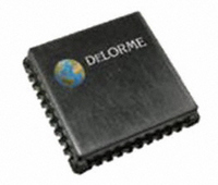
GM-205810-000 DeLorme, GM-205810-000 Datasheet

GM-205810-000
Specifications of GM-205810-000
Related parts for GM-205810-000
GM-205810-000 Summary of contents
Page 1
... GPS receiver subsystem are LNA, SAW Filter, RF front end, power conditioning, and the GPS baseband receiver itself. All these subsystems have been built into the DeLorme GPS module to eliminate the cost and time needed for the user to develop them independently. In simple terms, the user must connect an active or passive antenna, provide a power source, and connect the module to a host system via a serial port (or USB) to produce GPS positional data and enable a complete GPS receiver system ...
Page 2
Module Pinout Pin Descriptions Pin Name Function 1 Ground Power 2 VCC Power 3 nSTDBYO Output 4 nSTDBYI Input 5 WAKEUP Input 6 nRESET Input 7 AIN0 I/O 8 AIN1 I/O 9 AIN2 I/O 10 AIN3 I/O 11 VADC Power ...
Page 3
Block Diagram Typical Applications Page 3 ...
Page 4
Absolute Maximum Ratings Symbol V DD Voltage on VDD with respect to ground (VSS) V18 Voltage on optional 1.8V core supply input VADC Voltage on VADC pin with respect to ground (VSS Voltage on any pin with respect ...
Page 5
Mechanical Diagram RECOMMENDED PC BOARD LAYOUT UNITS MM & .068 1.73 .040 1.02 .020 R0.51 PACKAGE OUTLINE 3.07±0.05 PIN 1 INDICATOR 1.27±0.05 GPS2058 .450 11.43 .050 1.27 .652 16.56 .652 16.56 GPS2058 14.83±0.05 0.79±0.03 FR4 THICKNESS 40 ...
Page 6
... Ordering Information Ordering Code: GM-205810-000 Tape And Reel minimum order quantity: 500 units Tape Dimensions Page 6 ...
Page 7
Minimum Application Connectivity The following describes the minimum GPS2058 GPS receiver module connectivity necessary to obtain a position fix with passive antenna and host connection. The Antenna connects to the module on the RF-input pin very important that ...
Page 8
Power Supply Options The GPS2058 module can be powered by two different methods. The preferred method will depend on the supply voltages available on the PCB and the power consumption goals of the system. A single external 3.3V supply can ...
Page 9
STANDBY MODE In Standby mode, the CPU core is switched off to reduce power consumption. The Real Time Clock and Wake-Up logic remains independently powered by an internal low-power voltage regulator for fast start-ups coming out of Standby mode. The ...
Page 10
Hardware STANDBY To enter Standby mode via hardware requires bringing the nSTDBYI pin to a logic low state while the WAKEUP input is low. If the WAKEUP pin high logic level the GPS2058 will not enter Standby ...
Page 11
NMEA Output Messages When the GPS receiver is running a set of messages is presented on the NMEA port. These output strings are compatible with the NMEA 0183 standard and provide all the information needed by a navigation system. At ...
Page 12
Satellites in view, available as soon as the first satellite is acquired. It can be enabled/disabled with the $PDME,11 command. Note that this message is repeated MaxMsg times to report the status of all satellites in view (up to ...
Page 13
Geographic Position - Latitude/Longitude. It can be enabled/disabled with the $PDME,11 command. Message rate Message: $GPGLL,<Lat>,<LatRef>,<Lon>,<LonRef>,<PosUTC>,<Status>*checksum<cr><lf> Field Description Lat Latitude LatRef Latitude direction Lon Longitude LonRef Longitude Direction PosUTC Universal time coordinated Status Status A – Data ...
Page 14
... Command: Hot Start Format: $PDME,2<cr><If> Variables: None Return: If monitoring NMEA, the module will issue power-on start-up message (Delorme F/W and H/W versions are displayed), satellite vehicle NMEA message will maintain existing information but the active satellite message will indicate no fix ($GPGSA,A,1…). ...
Page 15
Command: Get Satellite Masking Angle Format: $PDME,7<cr><If> Variables: None Return: “$PDME,7,<maskang>” Operation: Returns the angle below which satellites are ignored; returned value is in whole degrees for the current GPS Library. Application: Informational; used with Set Mask Angle to establish ...
Page 16
Command: NMEA Messaging Configuration Format: $PDME,11,n1,h,n2<cr><If> Variables: All variables are independent of each other. n1= Baud Rate, acceptable values 4800 (default) 9600 19200 38400 57600 115200 h = Hex value to enable the corresponding NMEA message 0x01 = GGA 0x02 ...
Page 17
Command: System Control Set A, Return Estimated Position Error Format: $PDME,12,n<cr><If> Variables Return: “$PDME,12,<horizontal error>,<vertical error>” Operation: Returns a running statistical estimate of horizontal and vertical positional errors in meters. Application: Useful for general evaluation of accuracy, ...
Page 18
Recommended Reflow Profile The following graph shows a suggested reflow profile for an automated surface mount assembly processes. This reflow profile follows the recommendations for the lead-free solder used in the module assembly. The reflow process follows 4 complete stages: ...


