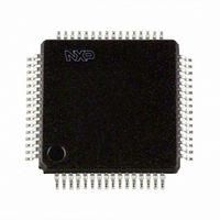
TEF6862HL/V1SS422: NXP Semiconductors, TEF6862HL/V1SS422: Datasheet - Page 32

TEF6862HL/V1SS422:
Manufacturer Part Number
TEF6862HL/V1SS422:
Description
IC TUNER CREST SELECTIVE 64LQFP
Manufacturer
NXP Semiconductors
Datasheet
1.TEF6862HLV1S518.pdf
(65 pages)
Specifications of TEF6862HL/V1SS422:
Modulation Or Protocol
AM, FM, WB
Applications
AM/FM Radio Receiver
Current - Receiving
101.9mA
Data Interface
PCB, Surface Mount
Antenna Connector
PCB, Surface Mount
Voltage - Supply
8 V ~ 9 V
Operating Temperature
-40°C ~ 85°C
Package / Case
64-LQFP
Lead Free Status / RoHS Status
Lead free / RoHS Compliant
Features
-
Frequency
-
Sensitivity
-
Memory Size
-
Data Rate - Maximum
-
Lead Free Status / RoHS Status
Lead free / RoHS Compliant, Lead free / RoHS Compliant
Other names
935289087557
Philips Semiconductors
TEF6862_1
Product data sheet
8.2.11.1 Factory alignment of IFCAP
8.2.11.2 Initialization of the radio
8.2.11.3 Factory alignment of IFCF
8.2.12 Write mode: data byte ACD
FM IF filter operation point alignment (data byte IFCAP): a single alignment of the FM IF
filter operation range secures an accurate and continuous frequency setting over the full
temperature range and all FM bands.
During radio initialization bit IFCAPA = 1 is used for writing the stored IFCAP alignment
value. Afterwards bit IFCAPA = 0. After the initialization repeated writing of the IFCAP
byte with the identical IFCAP alignment value is only allowed with bit IFCAPA = 0.
FM IF filter center frequency alignment (data byte IFCF): to correct IF frequency errors
caused by an error in the crystal frequency the alignment is preferably performed for every
FM band in use. A test frequency in the center of the band is preferred. An accurate
alignment result is realized by testing for symmetrical filter attenuation.
10. Set bit IFCFA = 0 to return to normal operation
Table 49.
1. Set bit IFCAPA = 1 to disable internal IFCAP control
2. Increase bit IFCAP from 0 upwards until I
3. Save this IFCAP setting as alignment value
4. Set bit IFCAPA = 0 to return to normal operation
1. Set RF generator level V
2. Set bit IFWB = 1 for better accuracy (20 kHz bandwidth)
3. Set bit IFCFA = 1 to enable fast settling of the filter frequency
4. Test high side of filter curve: tune to f
5. Change IFCF[5:0] from 0 to 63 and note the read result LEV[7:0] (level voltages)
6. Test low side of filter curve: tune to f
7. Change IFCF[5:0] from 0 to 63 and note the level voltages
8. Find the IFCF[5:0] value where both level curves cross (lowest difference) and save
9. Set bit IFWB = 0 to return to normal operation
TE0
ID) changes from logic 0 to logic 1
(Japan/OIRT)
(Japan/OIRT)
this IFCF[5:0] value
7
0
ACD - data byte Ah bit allocation with default setting
LAP1
6
1
Rev. 01 — 14 September 2006
LAP0
5
0
RF
= 200 V
BAL1
4
0
Car Radio Enhanced Selectivity Tuner (CREST)
RF
RF
+ 50 kHz (Europe/USA) or f
2
50 kHz (Europe/USA) or f
C-bus read bit IFCAPG (read data byte 4,
BAL0
3
1
WAM1
© Koninklijke Philips Electronics N.V. 2006. All rights reserved.
2
0
WAM0
TEF6862
RF
RF
1
1
+ 33.3 kHz
33.3 kHz
BWFLAG
32 of 65
0
0


