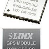
RXM-GPS-SG-T Linx Technologies Inc, RXM-GPS-SG-T Datasheet - Page 8

RXM-GPS-SG-T
Manufacturer Part Number
RXM-GPS-SG-T
Description
GPS MODULE SMD SIRF
Manufacturer
Linx Technologies Inc
Series
SGr
Type
GPS Moduler
Datasheet
1.MDEV-GPS-SG.pdf
(17 pages)
Specifications of RXM-GPS-SG-T
Package / Case
Module
Operating Voltage
4.2 V
Operating Current
46 mA
Frequency Range
1575.42 MHz
Interface Type
UART, USB
Operating Temperature Range
- 30 C to + 85 C
Lead Free Status / RoHS Status
Lead free / RoHS Compliant
Features
-
Voltage - Supply
-
Frequency
-
Operating Temperature
-
Applications
-
Sensitivity
-
Memory Size
-
Data Interface
-
Data Rate - Maximum
-
Modulation Or Protocol
-
Antenna Connector
-
Current - Receiving
-
Lead Free Status / Rohs Status
Lead free / RoHS Compliant
Table 9: Recommended Minimum Specific GNSS Data Example
Table 10: Course Over Ground and Ground Speed Example
Page 14
Message ID
UTC Time
Status
Latitude
N/S Indicator
Longitude
E/W Indicator
Speed over ground
Course over ground 79.65
Date
Magnetic Variation
Variation Sense
Mode
Checksum
<CR> <LF>
Message ID
Course over ground 79.65
Reference
Course over ground
Reference
Speed over ground
Units
Speed over ground
Units
Mode
Checksum
<CR> <LF>
RMC – Recommended Minimum Specific GNSS Data
VTG – Course Over Ground and Ground Speed
The table below contains the values for the following example:
The table below contains the values for the following example:
$GPRMC,053740.000,A,2503.6319,N,12136.0099,E,2.69,79.65,100106,,,A*53
Name
Name
$GPRMC
53740
A
2503.632
N
12136.01
E
2.69
100106
A
*53
$GPVTG
T
M
2.69
N
5
K
A
*38
Example
Example
$GPVTG,79.65,T,,M,2.69,N,5.0,K,A*38
knots
degrees
degrees
degrees
degrees
knots
km/hr
Units
Units
VTG protocol header
Measured heading
TRUE
Measured heading (N/A, Null Field)
Magnetic
Measured speed
Knots
Measured speed
Kilometer per hour
A=autonomous, E=DR
End of message termination
RMC protocol header
hhmmss.sss
A=data valid or V=data not valid
ddmm.mmmm
N=north or S=south
dddmm.mmmm
E=east or W=west
TRUE
ddmmyy
Not Available, Null Field
E=east or W=west (Not shown)
A=autonomous, D=DGPS, E=DR
End of message termination
Description
Description
NMEA INPUT MESSAGES
Table 11: Serial Data Structure
Table 12: Message ID Values
Start Sequence $PSRF
Message ID
Payload
Checksum
End Sequence
SetSerialPort
NavigationInitialization
Query/Rate Control
LLANavigationInitialization
Development Data On/Off
PowerManagement
StaticNavigation
SetIO
ReadInput
WriteOutput
Query
The following outlines the serial commands input into the module for
configuration. By default, the commands are input at 9,600bps, 8 data bits, no
parity, and 1 stop bit.
All fields in all proprietary NMEA messages are required; none are optional. All
NMEA messages are comma delimited.
The table below outlines the message identifiers supported by the module.
Name
Message
<MID>
DATA
CKSUM
<CR><LF>
Example
MID
100
101
103
104
105
200
202
211
212
213
215
Message Identifier consisting of three numeric
characters. Input messages begin at MID 100.
Message specific data.
CKSUM is a two-hex character checksum as
defined in the NMEA specification, NMEA-0183
Standard For Interfacing Marine Electronic Devices.
Checksums are required on all input messages.
Each message must be terminated using Carriage
Return (CR) Line Feed (LF) (\r\n, 0x0D0A) to cause
the receiver to process the input message. They are
not printable ASCII characters, so are omitted from
the examples.
Set PORT A parameters and protocol
Reset the modules
Query standard NMEA message and/or set
output rate
Reset the modules
Development Data messages On/Off
Sets the power performance of the receiver
Sets static navigation On/Off
Sets the I/O lines to an input or output
Reads the state of the inputs lines
Writes the state of an output line
Get configuration and current state of all GPIOs
Description
Description
Page 15


