RXM-GPS-SR-T Linx Technologies Inc, RXM-GPS-SR-T Datasheet - Page 8
RXM-GPS-SR-T
Manufacturer Part Number
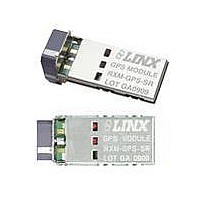
RXM-GPS-SR-T
Description
GPS MODULE SMD SIRF W/ANT
Manufacturer
Linx Technologies Inc
Series
SRr
Type
GPS Receiver Moduler
Datasheet
1.MDEV-GPS-SR.pdf
(15 pages)
Specifications of RXM-GPS-SR-T
Package / Case
Module
Operating Voltage
3 V to 4.3 V
Operating Current
31 mA
Frequency Range
1575.42 MHz
Interface Type
UART, USB
Operating Temperature Range
- 30 C to + 85 C
Lead Free Status / RoHS Status
Lead free / RoHS Compliant
Features
-
Voltage - Supply
-
Frequency
-
Operating Temperature
-
Applications
-
Sensitivity
-
Memory Size
-
Data Interface
-
Data Rate - Maximum
-
Modulation Or Protocol
-
Antenna Connector
-
Current - Receiving
-
Lead Free Status / Rohs Status
Lead free / RoHS Compliant


Table 12: SetSerialPort Example
1. SiRF protocol is only valid for 8 data bits, 1 stop bit, and no parity.
2. Default settings are NMEA protocol using 9,600 baud, 8 data bits, 1 stop bit, and no parity.
Page 14
Message ID $PSRF100
Protocol
Baud
DataBits
StopBits
Parity
Checksum
<CR><LF>
100 – SetSerialPort
Name
This command message is used to set the protocol (SiRF binary or NMEA)
and/or the communication parameters (baud rate). Generally, this command is
used to switch the module back to SiRF binary protocol mode where a more
extensive command message set is available. When a valid message is
received, the parameters are stored in battery-backed SRAM and the receiver
restarts using the saved parameters.
The table below contains the values for the following example:
Switch to SiRF binary protocol at 9600,8,N,1
For details on the SiRF binary protocol, please refer to SiRF’s Binary Protocol
Reference Manual.
0
9600
8
1
0
*0C
Example
$PSRF100,0,9600,8,1,0*0C
2
PSRF100 protocol header
0=SiRF binary, 1=NMEA
4800, 9600, 19200, 38400, 57600
8
1
0=None
End of message termination
1
1
1
Description
Table 13: NavigationInitialization Example
Table 14: ResetCfg Values
Message ID
ECEF X
ECEF Y
ECEF Z
ClkOffset
TimeOfWeek
WeekNo
ChannelCount 12
ResetCfg
Checksum
<CR><LF>
0x01
0x02
0x04
0x08
101 – NavigationInitialization
Hex
This command was used to initialize the receiver with the current position (in X,
Y, Z coordinates), clock offset, and time, enabling a faster fix. Increased receiver
sensitivity and the removal of Selective Availability (SA) have made this
unneccessary. The command is retained for its ability to reset the module, but
the initialization fields are no longer supported.
The table below contains the values for the following example:
Name
Hot Start – All data valid
Warm Start – Ephemeris cleared
Cold Start – Clears all data in memory
Clear Memory – Clears all data in memory and resets the receiver back
to factory defaults
$PSRF101
0
0
0
96000
0
0
4
*1F
Example
$PSRF101,0,0,0,96000,0,0,12,4*1F
Units
Description
PSRF101 protocol header
See Table 15
End of message termination
Description
Page 15
Related parts for RXM-GPS-SR-T
Image
Part Number
Description
Manufacturer
Datasheet
Request
R

Part Number:
Description:
GPS MODULE SMD SIRF
Manufacturer:
Linx Technologies Inc
Datasheet:

Part Number:
Description:
GPS MODULE SMD SIRF W/ANT
Manufacturer:
Linx Technologies Inc
Datasheet:

Part Number:
Description:
GPS MODULE SMD SIRF
Manufacturer:
Linx Technologies Inc
Datasheet:

Part Number:
Description:
HOLDER BATTERY 20MM COIN CR2032
Manufacturer:
Linx Technologies Inc
Datasheet:

Part Number:
Description:
CONN RPSMA BL CRJA-CPV 8.5" COAX
Manufacturer:
Linx Technologies Inc

Part Number:
Description:
CABLE RG174 RPSMA M/F 8.5"
Manufacturer:
Linx Technologies Inc

Part Number:
Description:
CABLE RG174 SMA M/F 8.5"
Manufacturer:
Linx Technologies Inc

Part Number:
Description:
CABLE RPSMA/SMA 8.5"
Manufacturer:
Linx Technologies Inc

Part Number:
Description:
CABLE MALE-NMALE 8' RG-58 RPSMA
Manufacturer:
Linx Technologies Inc

Part Number:
Description:
CABLE RPSMA/SMA 8.5"
Manufacturer:
Linx Technologies Inc

Part Number:
Description:
MODULE USB LOW SPEED
Manufacturer:
Linx Technologies Inc
Datasheet:

Part Number:
Description:
IC TRANSCODER MT BI-DIR 20-SSOP
Manufacturer:
Linx Technologies Inc
Datasheet:

Part Number:
Description:
IC ENCODER LOW SECURITY 8DIP
Manufacturer:
Linx Technologies Inc
Datasheet:

Part Number:
Description:
IC DECODER MS SERIES 20-SSOP
Manufacturer:
Linx Technologies Inc
Datasheet:
Part Number:
Description:
IC ENCODER MS SERIES 20-SSOP
Manufacturer:
Linx Technologies Inc
Datasheet: