WISMC03BI Laird Technologies, WISMC03BI Datasheet
WISMC03BI
Specifications of WISMC03BI


Related parts for WISMC03BI


WISMC03BI Summary of contents
Page 1
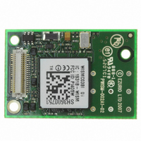
... Wireless LAN Module / Device Server UDP/SLIP (BISM Form Factor Compatible) Part Number: WISMC03BI 1. General Description EZURiO’s 802.11b/g SLIP Wireless LAN Module is a fully integrated and qualified wireless device server sub-system, designed to make it simple to embed 802.11 connectivity. It has been designed to be pin compatible with the footprint of Siemens MC55 GPRS modules, allowing designers to design one pcb to support either GPRS or Wireless LAN connectivity ...
Page 2
Applications • POS Equipment • Medical Equipment • Telematics • Metering Applications 2. Features Feature Wireless Specification Standards Supported Frequency Channels Max Transmit Power Receive Sensitivity Data Rates Data Transfer rate Modulation Schemes Range Connection Modes Antenna Modes Integrated Antenna ...
Page 3
Security Protocols Network Drivers Internet Power Consumption Powersave modes Current Consumption Supply Voltage Supply Regulation Embedded Wireless Processor System Specification WLAN functions Upgradeability Coexistence / Compatibility Bluetooth Connections Interface External Antenna Physical Dimensions Weight Environmental Operating Temperature Storage Temperature Approvals ...
Page 4
Block Diagram The module has a 40 way Hirose connector which provides a compatible pin out to the same form factor EZURiO Bluetooth Intelligent Serial Module. DSH_WISMC03_0v97 WISM 40 pin SLIP Data Sheet.doc © 2007-8 EZURiO Ltd Page 4 ...
Page 5
Mechanical 3.1 Wireless LAN Module Dimensional outline All dimensions in mm Notes 1 RF antenna 2 External Antenna connector (Hirose U.FL-R-SMT) 3 Board to board connector (Hirose connector) 4 2.0mm maximum top side component height (excluding antenna) 5 1.5mm ...
Page 6
Electrical 4.1 40 way Hirose Pin Descriptions The Hirose DF12C board-to-board connector on the module is a 40-pin double-row receptacle. The table below defines the pin functions. The pin-out is as viewed from the underside of the Module. Pin ...
Page 7
Electrical Specifications 4.1.1 Absolute Maximum ratings Absolute maximum ratings for supply voltage and voltages on digital and analogue pins of the Module are listed below. Exceeding these values will cause permanent damage. Parameter Peak current of power supply Voltage ...
Page 8
Other Functions Signal Name Pin No RESET 13 3VOUT 27 4.1.2.6 Signal Levels for Bluetooth Coexistence and Wakeup Pins Signal Type Signal level Input V max=1. min=1. max=3.5V IH Output V max=0. min=2.4V ...
Page 9
RF Performance 5.1 Transmit Power (802.11g) Conducted Transmit Power Antenna Gain (Integrated Antenna) Effective Transmit Power 5.2 Transmit Power (802.11b) Conducted Transmit Power Antenna Gain (Integrated Antenna) Effective Transmit Power 5.3 Receive Sensitivity (802.11b) Receive Sensitivity (11Mbps) Antenna Gain ...
Page 10
Functional Description The Wireless LAN module is designed for use with a host system that implements a TCP/IP stack. It provides a UDP stack and SLIP interface to allow fast integration. The integrated, high performance antenna together with the ...
Page 11
Note that the serial module output is at 3.0V CMOS logic levels. Level conversion must be added to interface with an RS-232 level compliant interface. 6.1.2 Bluetooth Coexistence Three pins are provided to allow implementation of Bluetooth coexistence schemes, when ...
Page 12
Firmware Features 7.1 Command Set The module supports the following commands. Details of the complete command list are provided in a separate Programming Guide, the following are a provided as an overview. Command Parameters UARTMODIFY Baud: Baud rate (9600, ...
Page 13
CFGGPIOOUTPUT CFGGPIOINPUT SETGPIO CLEARGPIO READGPIO 7.2 Power Saving The module supports the Wireless LAN IEEE power saving function. When this power saving mode is enabled, the wireless LAN chipset goes to sleep when it is not actively receiving from the ...
Page 14
Application Information 8.1 Antenna Location The antenna used on the Wireless LAN module is designed to be largely immune from the effects of proximity detuning. Normally, antennas operating at 2.4GHz are affected by their surroundings, so that great care ...
Page 15
The antenna finish may tarnish as a result of environmental conditions and handling. This is a cosmetic effect and does not affect the RF performance. 8.2 External Antenna The approval of the module was performed using a 3dBi external antenna ...
Page 16
Board to board connector and stacking height The WISM connects to a motherboard by means of a board-to-board connector that is supplied by Hirose. Mating headers from Hirose are available in different stacking heights, allowing the spacing between the ...
Page 17
... The label contains the Part number, firmware version loaded at manufacture, serial number and statutory approvals information. 8.10 Ordering Information The WISM described in this data sheet should be ordered using the part number below: Part Number WISMC03BI DSH_WISMC03_0v97 WISM 40 pin SLIP Data Sheet.doc Source EZURiO / Richco Richco ...
Page 18
Qualification 9.1 Qualification Process The following safety precautions must be observed during all phases of the operation, usage, service or repair of any application incorporating this Module. Manufacturers of the RF equipment are advised to convey the following safety ...
Page 19
Further details on the notification procedure are given in EZURiO’s Application Note AN016 - Notification Requirements for Wireless Products. 10. Related Documents AN008 - Wireless Development Kit User Guide AN016 - Notification Requirements for Wireless Products. AN017 – Interfacing to ...
Page 20
Disclaimers EZURIO’S WIRELESS PRODUCTS ARE NOT AUTHORISED FOR USE AS CRITICAL COMPONENTS IN LIFE SUPPORT DEVICES OR SYSTEMS WITHOUT THE EXPRESS WRITTEN APPROVAL OF THE MANAGING DIRECTOR OF EZURIO LTD. The definitions used herein are: a) Life support devices ...