RN-131C Roving Networks Inc, RN-131C Datasheet - Page 9
RN-131C
Manufacturer Part Number
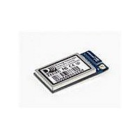
RN-131C
Description
MODULE WIFLY GSX 802.11 B/G U.FL
Manufacturer
Roving Networks Inc
Datasheet
1.RN-131G.pdf
(11 pages)
Specifications of RN-131C
Frequency
2.4GHz
Data Rate - Maximum
54Mbps
Modulation Or Protocol
802.11 b/g
Applications
General Purpose
Power - Output
18dBm
Sensitivity
-85dBm
Voltage - Supply
3 V ~ 3.7 V
Current - Receiving
40mA
Current - Transmitting
140mA
Data Interface
PCB, Surface Mount
Memory Size
8Mb Flash, 128kB RAM
Antenna Connector
On-Board, Chip, U.FL
Operating Temperature
0°C ~ 70°C
Package / Case
Module
Wireless Frequency
2.4 GHz
Modulation
CCK, DBPSK, DQPSK
Security
EAP, WPA, WPA2
Operating Voltage
3.3 V
Output Power
18 dBm
Antenna
Chip, U.FL Connector
Operating Temperature Range
- 30 C to + 85 C
Lead Free Status / RoHS Status
Lead free / RoHS Compliant
Lead Free Status / RoHS Status
Lead free / RoHS Compliant, Lead free / RoHS Compliant
Other names
740-1036
Available stocks
Company
Part Number
Manufacturer
Quantity
Price

Part Number:
RN-131C
Manufacturer:
MICROCHIP/微芯
Quantity:
20 000
Company:
Part Number:
RN-131C/RM
Manufacturer:
NXP
Quantity:
1 000


5. Connection Status. GPIO-4, GPIO-5, GPIO-6 are available to drive a status LEDs. GPIO-6 indicates TCP/IP
6. Keep out areas. When designing your PCB
7. Powering the module. The WiFly module can
8. Reset (Pin 5). The RESET signal is used to reset the module and is ACTIVE low. This pin has a built in 100k pull
9. Force Awake (Pin 9). This signal forces the module to wake up from sleep state. FORCE_AWAKE is active high
10. Achieving lowest power in sleep mode
connection status. This signal is ON high for an active connection, toggles fast to indicate no IP address and
toggles slow indicates IP address OK but not connection. GPIO-4 indicates association status. High means not
associated with a network, Off indicates associated and Internet access is OK. GPIO-5 toggles when data is
transferred.
avoid exposed trace and via beneath the module.
be powered from either 3.0VDC batteries or
3.3VDC regulated power.
up. It is not required to connect this pin and it can be left unconnected. To reset the module a pulse of 160us
minimum duration at 3.3V must be applied.
signal. To wake the module, a pulse of minimum 250 us at 3.3V must be applied.
To achieve the lowest power consumption (4uA) in sleep mode connect a weak pull down (100K resistor to GND)
on the following pin.
If GPIO-8 through GPIO-4 are being used to drive an output, connect a 100k pull down resistor. Any GPIOs not
used (No connect) can be left floating.
Other GPIO lines: No pulldown needed, internal pulldown ( 80K ) already on chip.
3.0VDC battery power
3.3 VDC power
www.rovingnetworks.com
Pin 22 - DMA-TX
Pin 25 - GPIO-8
Pin 26 - GPIO-7
Pin 27 - GPIO-6
Pin 28 - GPIO-5
Pin 29 - GPIO-4
809 University Avenue
Apply power to pin 20 (VDD-BATT)
Short pin 17 (3.3V-REG-OUT) to pin 18
(3.3V-REG-IN) (battery boost mode)
150mA of current at 3.3V available for
external devices on pin 21 when in
battery boost mode.
Apply power to pin 20(VDD-BATT) and
pin 21 (VDD-IN)
Connect pin 18 (3.3V-REG-IN) to ground and leave pin 17 (3.3V-REG-OUT) unconnected.
•
Los Gatos, CA 95032
~ page 9 ~
8.0 mm
•
Tel (408) 395-6539
6mm
Bottom view
RN-131G & RN-131C
• info@RovingNetworks.com
RN-131-DS v2.5 12/2/2010
5 mm
Keep out areas: There are two
1 mm round test pads on the
bottom of the module. Avoid
placing any exposed traces
or vias in these areas
3 mm
Related parts for RN-131C
Image
Part Number
Description
Manufacturer
Datasheet
Request
R

Part Number:
Description:
MODULE SOCKET BLUETOOTH CLASS1
Manufacturer:
Roving Networks Inc
Datasheet:

Part Number:
Description:
MODULE BLUETOOTH V2.1+EDR
Manufacturer:
Roving Networks Inc
Datasheet:

Part Number:
Description:
ANTENNA 2.4GHZ STUBBY 1"
Manufacturer:
Roving Networks Inc
Datasheet:

Part Number:
Description:
MODULE WIFLY 802.11B 1/4 WV-WIRE
Manufacturer:
Roving Networks Inc
Datasheet:

Part Number:
Description:
ANTENNA 2.4GHZ 4" SMA MALE
Manufacturer:
Roving Networks Inc
Datasheet:

Part Number:
Description:
ANTENNA 2.4GHZ 2.5" R/A SMA MALE
Manufacturer:
Roving Networks Inc
Datasheet:

Part Number:
Description:
ADAPTER BLUETOOTH FRFLY SRL FEML
Manufacturer:
Roving Networks Inc
Datasheet:

Part Number:
Description:
ADAPTER BLUETOOTH FRFLY SRL MALE
Manufacturer:
Roving Networks Inc
Datasheet:

Part Number:
Description:
ADAPTER BLUETOOTH USB DRIVERLESS
Manufacturer:
Roving Networks Inc
Datasheet:

Part Number:
Description:
ADAPTER BLUETOOTH FIREFLY RS422
Manufacturer:
Roving Networks Inc
Datasheet:

Part Number:
Description:
ANTENNA 2.4GHZ RPSMA
Manufacturer:
Roving Networks Inc
Datasheet:

Part Number:
Description:
ANTENNA 2.4GHZ 4 INCH W/RPSMA
Manufacturer:
Roving Networks Inc
Datasheet:

Part Number:
Description:
ADAPTER USB 1.1 TO SERIAL M/DB-9
Manufacturer:
Roving Networks Inc
Datasheet:
Part Number:
Description:
MODULE SOCKET BLUETOOTH CLASS1
Manufacturer:
Roving Networks Inc
Datasheet:
Part Number:
Description:
MODULE BLUETOOTH V2.1+EDR
Manufacturer:
Roving Networks Inc
Datasheet: