AC4490LR-200M Laird Technologies, AC4490LR-200M Datasheet - Page 19
AC4490LR-200M
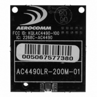
Manufacturer Part Number
AC4490LR-200M
Description
TXRX 900MHZ 3.3-5.5V TTL 200MW
Manufacturer
Laird Technologies
Series
AeroCommr
Specifications of AC4490LR-200M
Frequency
902MHz ~ 928MHz
Data Rate - Maximum
115.2kbps
Modulation Or Protocol
FHSS, FSK
Applications
AMR, Fire & Security Alarms, Telemetry
Power - Output
5mW ~ 200mW
Sensitivity
-110dBm
Voltage - Supply
3.3V, 5V
Current - Transmitting
68mA
Data Interface
Connector, 2 x 10 Header
Antenna Connector
MMCX
Operating Temperature
-40°C ~ 85°C
Package / Case
Module
Output Power
200 mW
Lead Free Status / RoHS Status
Contains lead / RoHS non-compliant
Memory Size
-
Current - Receiving
-
Lead Free Status / Rohs Status
Lead free / RoHS Compliant


4
S
I
ERIAL
NTERFACE
In order for the OEM Host and a transceiver to communicate over the serial interface they need to have the same
serial data rate. Refer to the following sections to ensure that the OEM Host data rate matches the serial interface
baud rate.
S E R I A L C O M M U N I C A T I O N S
The AC4490 is a TTL device which can be interfaced to a compatible UART (microcontroller) or level translator to allow
connection to serial devices. UART stands for Universal Asynchronous Receiver Transmitter and its main function is
to transmit or receive serial data.
A s y n c h r o n o u s O p e r a t i o n
Since there is no seperate clock in asynchronous operation, the receiver needs a method of synchronizing with the
transmitter. This is achieved by having a fixed baud rate and by using START and STOP bits. A typical asynchronous
mode signal is shown below.
F i g u r e 2 : A s y n c h r o n o u s M o d e S i g n a l
The UART outputs and inputs logic level signals on the TX and RX pins. The signal is high when no data is being
transmitted and goes low when transmission begins.
The signal stays low for the duration of the START bit and is followed by the data bits; LSB first. The STOP bit follows
the last data bit and is always high. After the STOP bit has completed, the START bit of the next transmission can
occur.
P a r i t y
A parity bit is used to provide error checking for a single bit error. When a single bit is used, parity can be either even
or odd. Even parity means that the number of ones in the data and parity sum to an even number and vice-versa. The
ninth data bit can be used as a parity bit if the data format requires eight data bits and a parity bit as shown below.
www.aerocomm.com
Related parts for AC4490LR-200M
Image
Part Number
Description
Manufacturer
Datasheet
Request
R

Part Number:
Description:
TXRX 900MHZ 3.3V TTL 1W
Manufacturer:
Laird Technologies
Datasheet:

Part Number:
Description:
Bluetooth Serial Module Development Kit
Manufacturer:
Laird Technologies
Part Number:
Description:
BLUETOOTH MODULE DEVELOPMENT KIT
Manufacturer:
Laird Technologies
Part Number:
Description:
Bluetooth 2.0 AT Data Module, Internal Antenna Development Kit
Manufacturer:
Laird Technologies

Part Number:
Description:
BLUETOOTH EVAL BOARD BTM511
Manufacturer:
Laird Technologies
Datasheet:

Part Number:
Description:
Bluetooth / 802.15.1 Modules & Development Tools BLUETTH Multimed MODLE, No ANT DEVKIT
Manufacturer:
Laird Technologies
Datasheet:

Part Number:
Description:
DEV KIT PRM122
Manufacturer:
Laird Technologies
Datasheet:
Part Number:
Description:
DEV KIT PRM123
Manufacturer:
Laird Technologies
Datasheet:

Part Number:
Description:
KIT FOR PRM112
Manufacturer:
Laird Technologies
Datasheet:
Part Number:
Description:
DEV KIT PRM121
Manufacturer:
Laird Technologies
Datasheet:

Part Number:
Description:
CHOKE COMMON MODE 110 OHMS SMD
Manufacturer:
Laird Technologies
Datasheet: