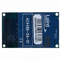
AC4486-5A-485 Laird Technologies, AC4486-5A-485 Datasheet - Page 24

AC4486-5A-485
Manufacturer Part Number
AC4486-5A-485
Description
TXRX 868MHZ 3V TTL 5MW RS485
Manufacturer
Laird Technologies
Series
AeroCommr
Specifications of AC4486-5A-485
Frequency
868MHz
Data Rate - Maximum
115.2kbps
Modulation Or Protocol
FSK
Applications
AMR, Gaming Devices, Inventory Tracking
Power - Output
5mW
Sensitivity
-100dBm
Voltage - Supply
3.3V
Current - Receiving
30mA
Current - Transmitting
40mA
Data Interface
Connector, 2 x 10 Header
Antenna Connector
On-Board, Chip
Operating Temperature
-40°C ~ 85°C
Package / Case
Module
Board Size
49 mm x 42 mm x 5 mm
Output Power
5 mW
Antenna
External MMCX Connector
Lead Free Status / RoHS Status
Lead free / RoHS Compliant
Memory Size
-
Lead Free Status / Rohs Status
Lead free / RoHS Compliant
AC4486 Specifications
4.5.2 AT Enter Configuration Mode
In order to send configuration commands via AT Command mode, Configuration mode must be
entered. Once in Configuration mode, standard configuration commands can be sent to the
transceiver including the Exit Configuration Mode command. Upon sending the Exit Configuration
mode command, the transceiver will return to AT Command mode. When in AT Command mode,
Configuration mode can be entered by sending the following command to the transceiver:
Host Command:
Transceiver Response:
4.5.3 Exit AT Command Mode
To exit AT Command mode, the OEM host should send the following command to the transceiver:
Host Command:
Transceiver Response:
4.6 O
The AC4486 transceiver contains static memory that holds many of the parameters that control the
transceiver operation. Using the “CC” command set allows many of these parameters to be changed
during system operation. Because the memory these commands affect is static, when the transceiver
is reset, these parameters will revert back to the settings stored in the EEPROM. Note: Do not to
modify undocumented static addresses as undesired operation may occur. All “CC” commands must
be issued from the Host to the transceiver with Command/Data (Pin 17) pulled logic Low. To exit “CC”
mode, simply take the Command/Data pin High.
While in CC Command mode (using pin 17, Command/Data), the RF interface of the transceiver is still
active. Therefore, it can receive packets from remote transceivers while in CC Command mode and
forwards these to the OEM Host. While in CC Command mode (using AT Commands), the RF
interface of the transceiver is active, but packets sent from other transceivers will not be received. The
transceiver uses Interface Timeout/Fixed Packet Length to determine when a CC Command is
complete. Therefore, there should be no delay between each character as it is sent from the OEM
Host to the transceiver or the transceiver will not recognize the command and will enter Configuration
Mode by default. If the OEM Host has sent a CC Command to the transceiver and a RF packet is
received by the transceiver, the transceiver will send the CC Command response to the OEM Host
before sending the packet. However, if a RF packet is received before the Interface Timeout expires
on a CC Command, the transceiver will send the packet to the host before sending the CC Command
response.
01/21/05
CCh 65h
65h
CCh ATO↵
Hexadecimal Representation of the Command:
CCh, 41h, 54h, 4Fh, 0Dh
CCh DAT
Hexadecimal Representation of the Command:
CCh, 44h, 41h, 54h
N
-
THE
-F
LY
C
ONTROL
C
OMMANDS
(CC C
OMMAND
M
ODE
)
24


