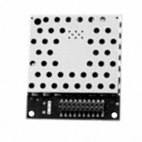
AC4790-200M-485 Laird Technologies, AC4790-200M-485 Datasheet - Page 25

AC4790-200M-485
Manufacturer Part Number
AC4790-200M-485
Description
TXRX 900MHZ 3.3-5.5V FHSS 200MW
Manufacturer
Laird Technologies
Series
AeroCommr
Specifications of AC4790-200M-485
Frequency
902MHz ~ 928MHz
Data Rate - Maximum
115.2kbps
Modulation Or Protocol
FHSS, FSK
Applications
AMR, Fire & Security Alarms, Telemetry
Power - Output
5mW ~ 200mW
Sensitivity
-110dBm
Voltage - Supply
3.3V, 5V
Current - Transmitting
68mA
Data Interface
Connector, 2 x 10 Header
Antenna Connector
MMCX
Operating Temperature
-40°C ~ 85°C
Package / Case
Module
Wireless Frequency
900 MHz
Interface Type
20-pin mini connector
Board Size
49 mm x 42 mm x 5 mm
Modulation
FHSS, FSK
Security
1 byte System ID, DES
Operating Voltage
3.3 V to 5.5 V
Output Power
200 mW
Antenna
Integral and External Dipole
Lead Free Status / RoHS Status
Contains lead / RoHS non-compliant
Memory Size
-
Current - Receiving
-
Lead Free Status / Rohs Status
Lead free / RoHS Compliant
H
Below is a description of all hardware pins used to control the AC4790.
P I N D E F I N I T I O N S
G e n e r i c I / O
Both GIn pins serve as generic input pins. When Protocol Status (byte 0xC2 of EEPROM) is disabled, GO0 & GO1
serve as generic outputs. When Protocol Status is enabled, pins GO0 and GO1 alternatively serve as the Session
Status and Receive Acknowledge Status pins, respectively. Reading and writing of these pins can be performed using
CC Commands.
When the GO0 pin is configured as the Session Status pin, GO0 is normally Low. GO0 will go High when a Session is
initiated and remain High until the end of the Session. When the GO1 pin is configured as the Receive Acknowledge
Status pin, GO1 is normally Low and GO1 will go High upon receiving a valid RF Acknowledgement and will remain
High until the end (rising edge) of the next hop.
T X D & R X D
The AC4790-200 accepts 3.3 or 5VDC TTL level asynchronous serial data on the RXD pin and interprets that data as
either Command Data or Transmit Data. Data is sent from the transceiver, at 3.3V levels, to the OEM Host via the TXD
pin. Note: The AC4790-1000 & AC4790-1x1 transceivers ONLY accept 3.3V level signals.
When equipped with an onboard RS-485 interface chip, TXD and RXD become the half duplex RS-485 pins. The
transceiver interface will be in Receive Mode except when it has data to send to the OEM Host. TXD is the non-
inverted representation of the data (RS485A) and RXD is a mirror image of TXD (RS485B). The transceiver will still use
RTS (if enabled).
C T S
The AC4790 has an interface buffer size of 256 bytes. If the buffer fills up and more bytes are sent to the transceiver
before the buffer can be emptied, data loss will occur. The transceiver prevents this loss by asserting CTS High as the
buffer fills up and taking CTS Low as the buffer is emptied. CTS On and CTS Off control the operation of CTS. CTS On
specifies the amount of bytes that must be in the buffer for CTS to be disabled (logic High). Even while CTS is
disabled, the OEM Host can still send data to the transceiver, but it should do so carefully.
Note: The CTS On/Off bytes of the EEPROM can be set to 1, in which case CTS will go high as data is sent in and low
when buffer is empty.
R T S
With RTS disabled, the transceiver will send any received data to the OEM Host as soon as it is received. However,
some OEM Hosts are not able to accept data from the transceiver all of the time. With RTS enabled, the OEM Host can
ARDWARE
H A R D W A R E P R O T O C O L S T A T U S
S E R I A L T T L
R S - 4 8 5
I
NTERFACE
www.lairdtech.com\wireless
5


