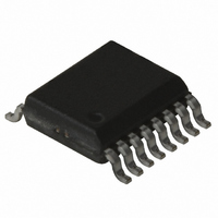
TH7107EFC Melexis Inc, TH7107EFC Datasheet

TH7107EFC
Specifications of TH7107EFC
TH7107EFF
Related parts for TH7107EFC
TH7107EFC Summary of contents
Page 1
Features ! Fully integrated, PLL-stabilized VCO ! Frequency range from 310 MHz to 440 MHz ! FSK through crystal pulling allows modulation from kbit/s ! High FSK deviation possible for wideband data transmission ! ASK achieved by ...
Page 2
Document Content 1 Theory of Operation ...................................................................................................3 1.1 General............................................................................................................................... 3 1.2 Block Diagram .................................................................................................................... 3 2 Functional Description ..............................................................................................4 2.1 FSK Modulation .................................................................................................................. 4 2.2 Frequency Modulation ........................................................................................................ 4 2.3 ASK Modulation.................................................................................................................. 4 2.4 Mode Control Logic............................................................................................................. 4 3 Pin ...
Page 3
Theory of Operation 1.1 General As depicted in Fig.1, the TH7107 transmitter consists of a fully integrated voltage-controlled oscillator (VCO), a divide-by-32 divider (div32), a phase-frequency detector (PFD) and a charge pump. An external loop filter at pin LF ...
Page 4
Functional Description 2.1 FSK Modulation A Colpitts crystal oscillator (XOSC) is used as the reference oscillator of a phase-locked loop (PLL) synthe- sizer. FSK modulation is achieved by pulling the crystal (XTAL) through the data CMOS-compatible data ...
Page 5
Pin Definition and Description Pin No. Name I/O Type 1 LF1 output 2 SUB ground 3 DATA input 4 RO2 analog I/O 5 RO1 analog I/O 6 ENTX input 7 ENCK input 3901007107 Rev. 008 FSK/FM/ASK Transmitter Functional Schematic ...
Page 6
Pin No. Name I/O Type 8 CKOUT output 9 PS analog I/O 10 VCC supply 11 VEE ground 12 OUT2 output 13 OUT1 output 14 VEE ground 15 VCC supply 16 LF2 input 3901007107 Rev. 008 Functional Schematic CKOUT 200 ...
Page 7
Electrical Characteristics 4.1 Absolute Maximum Ratings Parameter Supply voltage Input voltage Storage temperature Junction temperature Thermal Resistance Power dissipation Electrostatic discharge 1) all pins except OUT1, OUT2 4.2 Normal Operating Conditions Parameter Supply voltage Operating temperature Input low voltage ...
Page 8
DC Characteristics all parameters under normal operating conditions, unless otherwise stated; typical values °C and V A Parameter Symbol Standby current Clock only current Operating current Input current Pull down current Pull up current MOS ...
Page 9
Crystal Pulling 5.1 Center Frequency as Function of CX1 and CX2 The center frequency f is defined typical values °C and V A XTAL = 13.55 MHz, Cload = 15 pF, shown ...
Page 10
Frequency Deviation as Function of CX1 and CX2 The frequency deviation ∆f is defined as (f typical values °C and V A XTAL = 13.55 MHz, Cload = 15 pF, shown in Fig. 3 CX1 ...
Page 11
Test Circuit Fig. 4: Test circuit for FSK, ASK and FM; with 50 matching network 6.1 Test circuit component list (Fig. 4) Part Size Value CF1 0603 10 nF CF2 0603 12 pF CX1 0603 39 pF _FSK CX1 ...
Page 12
Spectrum Plots All plots depict TH7107‘s typical performance at V derived with the test circuit shown in Fig. 4. Fig output signal and spurious emissions, CW mode (DATA = HIGH) Fig. 6: Single-sideband phase noise at 500 ...
Page 13
Fig. 7: FSK modulation with R Fig. 8: ASK modulation with R Fig with kHz, FM input signal with 1 V mod 3901007107 Rev. 008 FSK/FM/ASK Transmitter = 6.6 kbit/s NRZ FSK = 4 kbit/s ...
Page 14
Package Information .10 (.004) Fig. 10: QSOP16 (Quarter size Small Outline Package) all Dimension in mm, coplanarity < 0.1mm min 4.80 3.81 5.79 max 4.98 3.99 6.20 all Dimension in inch, coplanarity ...
Page 15
Reliability Information Melexis devices are classified and qualified regarding suitability for infrared, vapor phase and wave soldering with usual (63/37 SnPb-) solder (melting point at 183degC). The following test methods are applied: IPC/JEDEC J-STD-020A (issue April 1999) Moisture/Reflow Sensitivity ...
Page 16
Disclaimer Devices sold by Melexis are covered by the warranty and patent indemnification provisions appearing in its Term of Sale. Melexis makes no warranty, express, statutory, implied description regarding the information set forth herein or regarding the ...


