STEVAL-TDR028V1 STMicroelectronics, STEVAL-TDR028V1 Datasheet - Page 8
STEVAL-TDR028V1
Manufacturer Part Number
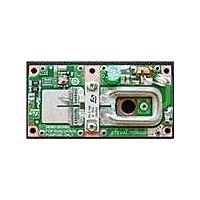
STEVAL-TDR028V1
Description
BOARD DEMO RF PWR AMP STAC2942B
Manufacturer
STMicroelectronics
Type
Power Amplifierr
Specifications of STEVAL-TDR028V1
Contents
Board
Maximum Operating Temperature
+ 70 C
Operating Supply Voltage
48 V
Product
Power Management Development Tools
For Use With/related Products
STAC2942B
Lead Free Status / RoHS Status
Lead free / RoHS Compliant
Other names
497-10763


STAC2942B mounting recommendations
4.7.2
4.8
8/11
material set featuring low creep and fatigue resistance, the complete system insures that
pressure is maintained uniformly over time.
Procedure
Tighten both fastener systems to each end of the package body to a “finger-tight” condition,
approximately 0.4 in-lb (0.05 N-m, 0.5 kg-cm).
Use a torque driver or equivalent means to tighten both screws to the recommended torque
of 5 in-lbs (0.6 N-m, 5.8 kg-cm).
Depending upon the choice of TIM, the required torque may be adjusted within the following
ranges without mechanical damage to the device:
●
●
Electrical connection
Leads and/or flanges should be attached to the PCB and/or copper heatsinks using typical
Sn63Pb37 or Pb-free solders, in accordance with the supplier's recommendations.
However, the following guidelines with respect to the package should be considered:
●
●
●
●
●
●
Min.: 3.5 in-lb (0.4 N-m, 4 kg-cm)
Max.: 6.5 in-lb (0.75 N-m, 7.5 kg-cm)
Avoid, as much as possible, the use of flux or flux solutions as it is a potential source of
contamination to the device.
The leads of the transistor may be tinned prior to assembly into the PCB. This practice
is used in situations when it is undesirable to introduce even a small amount of gold into
the solder composition, forestalling the possibility of solder embrittlement issues. The
source of Au stems from the lead and/or backside surfaces, which are plated with 40 to
100 µin (1 to 2.5 µm) of Au.
The amount of solder to be used depends on the type of solder and the amount of
allowable Au in the final solder composition. It is desirable to increase the amount of
solder when Au content is a concern, such as in Pb-free soldering applications.
It is recommended to use either a solder preform or solder paste having a thickness of
0.001 to 0.010 in (0.03 to 0.3 mm), typically 0.006 in (.15 mm).
Adjustment of the solder preform or paste thickness may be used advantageously to
account for thickness variations in the PCB manufacturing process.
In cases where the backside of the flange is soldered to a copper core or heatsink, the
package design and previously discussed mechanical mounting procedure provide
sufficient downward pressure on the solder preform, resulting in a thin, high-quality
bondline after a typical solder reflow procedure. In such cases, solder-wells or a solder-
moat around the perimeter of the flange should be considered, to provide a region for
excess solder to flow.
Doc ID 17469 Rev 1
STEVAL-TDR028V1
Related parts for STEVAL-TDR028V1
Image
Part Number
Description
Manufacturer
Datasheet
Request
R

Part Number:
Description:
BOARD EVAL FOR ST802RT1
Manufacturer:
STMicroelectronics
Datasheet:

Part Number:
Description:
EVAL BOARD 100 BASE T
Manufacturer:
STMicroelectronics
Datasheet:

Part Number:
Description:
BOARD ELECT FISCAL CASH REGISTER
Manufacturer:
STMicroelectronics
Datasheet:
Part Number:
Description:
BOARD EVAL FOR ST802RT1A
Manufacturer:
STMicroelectronics
Datasheet:

Part Number:
Description:
2 kW/100 V RF demonstration board for 3 T MRI based on the STAC4932B
Manufacturer:
STMICROELECTRONICS [STMicroelectronics]
Datasheet:

Part Number:
Description:
BOARD EVAL FOR MEMS SENSORS
Manufacturer:
STMicroelectronics
Datasheet:
Part Number:
Description:
EVALBOARD/STEVAL-ISV014V1
Manufacturer:
STMicroelectronics

Part Number:
Description:
BOARD EVAL FOR VACUUM CLEANER
Manufacturer:
STMicroelectronics
Datasheet:

Part Number:
Description:
KIT DEV STARTER ST10F276Z5
Manufacturer:
STMicroelectronics
Datasheet:

Part Number:
Description:
BOARD LED CTLR/DVR STLED316S
Manufacturer:
STMicroelectronics
Datasheet:
Part Number:
Description:
STMicroelectronics [RIPPLE-CARRY BINARY COUNTER/DIVIDERS]
Manufacturer:
STMicroelectronics
Datasheet:
Part Number:
Description:
STMicroelectronics [LIQUID-CRYSTAL DISPLAY DRIVERS]
Manufacturer:
STMicroelectronics
Datasheet:
Part Number:
Description:
BOARD EVAL FOR MEMS SENSORS
Manufacturer:
STMicroelectronics
Datasheet: