28140 Parallax Inc, 28140 Datasheet - Page 4
28140
Manufacturer Part Number
28140
Description
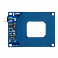
READER MODULE RFID
Manufacturer
Parallax Inc
Specifications of 28140
Rf Type
Read Only
Frequency
125kHz
Features
Single 5V Power Supply
Package / Case
Module
Product
Microcontroller Accessories
Data Bus Width
8 bit
Clock Speed
125 KHz
Interface Type
USB
Operating Supply Voltage
5.5 V
Board Size
46.99 mm x 69.22 mm x 21.84 mm
Lead Free Status / RoHS Status
Lead free / RoHS Compliant
Lead Free Status / RoHS Status
Lead free / RoHS Compliant, Lead free / RoHS Compliant


Usage
A visual indication of the state of the RFID Card Reader is given with the on-board LED. When the
module is successfully powered-up and is in an idle state, the LED will be GREEN. When the module is in
an active state searching for or communicating with a valid tag, the LED will be RED.
The RFID Card Reader Serial version is activated via the /ENABLE pin on the module’s 4-pin header.
When the RFID Card Reader is powered and /ENABLE is pulled LOW, the module will enter the active
state. When /ENABLE is pulled HIGH or left unconnected, the module will enter the idle state.
The RFID Card Reader USB version is activated via the DTR line of the USB Virtual COM port. When the
DTR line is set HIGH, the module will enter the active state. When the DTR line is set LOW, the module
will enter the idle state.
The face of the RFID tag should be held parallel to the front or back face of the antenna (where the
majority of RF energy is emitted). If the tag is held sideways (for example, perpendicular to the
antenna), you’ll either get no reading or a poor reading distance. Only one transponder tag should be
held up to the antenna at any time. The use of multiple tags at one time will cause tag collisions and the
reader may not detect any of them. The tags available in the Parallax store have a read distance of
approximately 4 inches. Actual distance may vary slightly depending on the size of the transponder tag
and environmental conditions of the application.
Communication Protocol
All communication is 8 data bits, no parity, 1 stop bit, and least significant bit first (8N1) at 2400 bps.
The RFID Card Reader Serial version transmits data as 5V TTL-level, non-inverted asynchronous serial.
The RFID Card Reader USB version transmits the data through the USB Virtual COM Port driver. This
allows easy access to the serial data stream from any software application, programming language, or
interface that can communicate with a COM port.
When the RFID Card Reader is active and a valid RFID transponder tag is placed within range of the
activated reader, the tag’s unique ID will be transmitted as a 12-byte printable ASCII string serially to the
host in the following format:
Start Byte
Unique ID
Unique ID
Unique ID
Unique ID
Unique ID
Unique ID
Unique ID
Unique ID
Unique ID
Unique ID
Stop Byte
(0x0A)
Digit 1
Digit 2
Digit 3
Digit 4
Digit 5
Digit 6
Digit 7
Digit 8
Digit 9
Digit 10
(0x0D)
The start byte and stop byte are used to easily identify that a correct string has been received from the
reader (they correspond to line feed and carriage return characters, respectively). The middle ten bytes
are the actual tag's unique ID. For example, for a tag with a valid ID of 0F0184F07A, the following bytes
would be sent: 0x0A, 0x30, 0x46, 0x30, 0x31, 0x38, 0x34, 0x46, 0x30, 0x37, 0x41, 0x0D.
Interference
The Parallax RFID Card Reader, like many RF devices, may experience RF noise in its frequency range.
This may cause the reader to transmit a spurious tag response when no tag is near the unit. This will not
affect most uses of the RFID Card Reader. To avoid treating spurious responses as legitimate tags, it is
recommended to read two responses in a row within a given amount of time (for example, one second)
to ensure that you are reading a valid tag and not a “tag” generated by noise.
Copyright © Parallax Inc.
RFID Card Reader Serial & USB (#28140 / 28340)
v2.2 3/22/2010 Page 4 of 11
Related parts for 28140
Image
Part Number
Description
Manufacturer
Datasheet
Request
R


Part Number:
Description:
Microcontroller Modules & Accessories DISCONTINUED BY PARALLAX
Manufacturer:
Parallax Inc

Part Number:
Description:
BOOK UNDERSTANDING SIGNALS
Manufacturer:
Parallax Inc
Datasheet:


Part Number:
Description:
COMPETITION RING FOR SUMOBOT
Manufacturer:
Parallax Inc
Datasheet:


Part Number:
Description:
TEXT INFRARED REMOTE FOR BOE-BOT
Manufacturer:
Parallax Inc
Datasheet:
Part Number:
Description:
BOARD EXPERIMENT+LCD NX-1000
Manufacturer:
Parallax Inc
Datasheet:

Part Number:
Description:
CONTROLLER 16SERVO MOTOR CONTROL
Manufacturer:
Parallax Inc
Datasheet:

Part Number:
Description:
BASIC STAMP LOGIC ANALYZER
Manufacturer:
Parallax Inc
Datasheet:

Part Number:
Description:
IC MCU 2K FLASH 50MHZ SO-18
Manufacturer:
Parallax Inc
Datasheet: