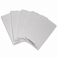
DLP-RFIDTAG DLP Design Inc, DLP-RFIDTAG Datasheet - Page 2

DLP-RFIDTAG
Manufacturer Part Number
DLP-RFIDTAG
Description
RFID TRANSPONDER TAGS HF 10-PACK
Manufacturer
DLP Design Inc
Datasheet
1.DLP-RFID1-OG.pdf
(7 pages)
Specifications of DLP-RFIDTAG
Rf Type
Read / Write
Frequency
13.56MHz
Features
ISO15693, ISO18000-3, Tag-it™
Package / Case
Card
Product
RFID Transponders
Dimensions
60.6 mm x 34.6 mm
Antenna
On-Board
Operating Temperature Range
0 C to + 70 C
Lead Free Status / RoHS Status
Lead free / RoHS Compliant
Lead Free Status / RoHS Status
Lead free / RoHS Compliant, Lead free / RoHS Compliant
Other names
813-1014
2.0 RFID BASICS
RFID stands for Radio Frequency IDentification. It is an electronic technology whereby digital data
encoded in an RFID Tag (or transponder) is retrieved utilizing a reader. In contrast to bar code
technology, RFID systems do not require line-of-sight access to the tag in order to retrieve the tag’s data,
and they are well suited to harsh environments.
An RFID tag consists of an integrated circuit attached to an antenna. In the case of the tags used with
the DLP-RFID1, the antenna is in the form of conductive ink “printed” on a material that allows for
connection to the integrated circuit. This type of passive (battery-free) tag is commonly referred to as an
“inlay”.
The RFID reader (or “interrogator”) is typically a microcontroller-based radio transceiver that powers the
tag with a time-varying electromagnetic radio frequency (RF) field. When the RF field passes through the
tag’s antenna, AC voltage is generated in the antenna and rectified to supply power to the tag. Once
powered, the tag can receive commands from the reader. The information stored in the tag can then be
read by the reader and sent back to the host PC for processing.
The data in the tag consists of a hard-coded, permanent serial number (or UID) and user memory that
can be written to, read from and locked if desired. Once locked, user data can still be read but not
changed.
3.0 SPECIFICATIONS
** See Integral Antenna Section for important regulatory details.
4.0 PERMANENT READER SERIAL NUMBER
Each DLP-RFID1 contains a unique, 32-bit, hard-coded serial number that cannot be altered by any
means. The serial number can be read via the USB interface and used to identify the reader via the host
software.
Rev 1.2 (May 2007)
* Limited Support – See Supported Tag Library Functions for details.
Reader Frequency
Output Power
Range (Integral Antenna)
Tags/Protocols Supported
Communications Interface
Operational Power – Active
Operational Power – Idle
Antenna
USB Driver Support
Physical Dimensions – OEM
Physical Dimensions – Retail
Operating Temperature
13.56MHz
200mW MAX
4 Inches MAX
Tag-It*, ISO18000-3, ISO15693
USB 1.1/2.0 Compatible, Mini-B 5-Pin Connector
120mA
15mA
On-Board Antenna, SMA Position Available**
Windows XP, XPx64, Server2003, 2000, 98, ME
PCB: .20x2.17x3.12” typ. (5.1x55.1x79.3mm)
Enclosure: .83x2.3x3.25” typ. (21.1x58.4x82.6mm)
0-70°C
2
DLP Design, Inc.


