T40HFL20S02 Vishay, T40HFL20S02 Datasheet - Page 5
T40HFL20S02
Manufacturer Part Number
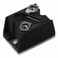
T40HFL20S02
Description
DIODE FAST REC 200V 40A D-55
Manufacturer
Vishay
Datasheet
1.T40HFL20S02.pdf
(15 pages)
Specifications of T40HFL20S02
Current - Reverse Leakage @ Vr
100µA @ 200V
Current - Average Rectified (io) (per Diode)
40A
Voltage - Dc Reverse (vr) (max)
200V
Reverse Recovery Time (trr)
200ns
Diode Type
Standard
Speed
Fast Recovery =< 500ns, > 200mA (Io)
Diode Configuration
Single
Mounting Type
Chassis Mount
Package / Case
D-55
Product
Fast Recovery Rectifier
Configuration
Single
Reverse Voltage
200 V
Forward Voltage Drop
1.6 V
Recovery Time
200 ns
Forward Continuous Current
40 A
Max Surge Current
500 A
Reverse Current Ir
100 uA
Mounting Style
Screw
No. Of Phases
Single
Repetitive Reverse Voltage Vrrm Max
200V
Forward Current If(av)
40A
Forward Voltage Vf Max
1.6V
Module Configuration
Single
Peak Reflow Compatible (260 C)
Yes
Lead Free Status / RoHS Status
Lead free / RoHS Compliant
Voltage - Forward (vf) (max) @ If
-
Lead Free Status / RoHS Status
Lead free / RoHS Compliant, Lead free / RoHS Compliant
Other names
*T40HFL20S02


Document Number: 93184
Revision: 19-May-10
100
70
60
50
40
30
20
10
Fig. 7 - Forward Power Loss Characteristics
90
80
70
60
50
40
30
20
10
Fig. 8 - Forward Power Loss Characteristics
Fig. 9 - Forward Power Loss Characteristics
90
80
70
60
50
40
30
20
10
0
0
0
0
0
0
RMS Limit
180°
120°
DC
5
90°
60°
30°
10
10
Average F orward Current (A)
Average Forward Current (A)
Average F orward Current (A)
RMS Limit
180°
120°
10
90°
60°
30°
RMS Limit
20
20
180°
120°
90°
60°
30°
15
DiodesAmericas@vishay.com, DiodesAsia@vishay.com,
30
30
For technical questions within your region, please contact one of the following:
20
Conduc tion Period
40
Conduc tion Angle
40
Conduc tion Angle
T 40HF L.. S eries
T = 125°C
T 70HF L.. S eries
T = 125°C
T 40HF L.. S eries
T = 125°C
J
25
J
J
50
50
30
60
60
35
(T-Modules), 40 A/70 A/85 A
40
70
70
Fast Recovery Diodes
T40HFL, T70HFL, T85HFL Series
140
120
100
160
140
120
100
DiodesEurope@vishay.com
110
100
Fig. 10 - Forward Power Loss Characteristics
Fig. 11 - Forward Power Loss Characteristics
Fig. 12 - Forward Power Loss Characteristics
80
60
40
20
80
60
40
20
90
80
70
60
50
40
30
20
10
0
0
0
0
0
0
RMS Limit
RMS Limit
180°
120°
180°
120°
10 20 30 40 50 60 70 80 90
DC
90°
60°
30°
DC
90°
60°
30°
20
Average F orward Current (A)
Average F orward Current (A)
20
Average Forward Current (A)
180°
120°
RMS Limit
90°
60°
30°
40
Vishay Semiconductors
40
60
60
Conduc tion Period
Conduc tion Period
80
Conduc tion Angle
T 85HFL.. S eries
T = 125°C
T 70HF L.. S eries
T = 125°C
T 85HFL.. S eries
T = 125°C
J
J
J
80
100
100
120
140
www.vishay.com
120
5
Related parts for T40HFL20S02
Image
Part Number
Description
Manufacturer
Datasheet
Request
R

Part Number:
Description:
357-036-542-201 CARDEDGE 36POS DL .156 BLK LOPRO
Manufacturer:
Vishay
Datasheet:
Part Number:
Description:
357-036-542-201 CARDEDGE 36POS DL .156 BLK LOPRO
Manufacturer:
Vishay
Datasheet:
Part Number:
Description:
357-036-542-201 CARDEDGE 36POS DL .156 BLK LOPRO
Manufacturer:
Vishay
Datasheet:
Part Number:
Description:
357-036-542-201 CARDEDGE 36POS DL .156 BLK LOPRO
Manufacturer:
Vishay
Datasheet:
Part Number:
Description:
357-036-542-201 CARDEDGE 36POS DL .156 BLK LOPRO
Manufacturer:
Vishay
Datasheet:
Part Number:
Description:
357-036-542-201 CARDEDGE 36POS DL .156 BLK LOPRO
Manufacturer:
Vishay
Datasheet:
Part Number:
Description:
357-036-542-201 CARDEDGE 36POS DL .156 BLK LOPRO
Manufacturer:
Vishay
Datasheet:
Part Number:
Description:
357-036-542-201 CARDEDGE 36POS DL .156 BLK LOPRO
Manufacturer:
Vishay
Datasheet:
Part Number:
Description:
357-036-542-201 CARDEDGE 36POS DL .156 BLK LOPRO
Manufacturer:
Vishay
Datasheet:
Part Number:
Description:
357-036-542-201 CARDEDGE 36POS DL .156 BLK LOPRO
Manufacturer:
Vishay
Datasheet:
Part Number:
Description:
357-036-542-201 CARDEDGE 36POS DL .156 BLK LOPRO
Manufacturer:
Vishay
Datasheet:
Part Number:
Description:
357-036-542-201 CARDEDGE 36POS DL .156 BLK LOPRO
Manufacturer:
Vishay
Datasheet:
Part Number:
Description:
357-036-542-201 CARDEDGE 36POS DL .156 BLK LOPRO
Manufacturer:
Vishay
Datasheet:
Part Number:
Description:
357-036-542-201 CARDEDGE 36POS DL .156 BLK LOPRO
Manufacturer:
Vishay
Datasheet:
Part Number:
Description:
357-036-542-201 CARDEDGE 36POS DL .156 BLK LOPRO
Manufacturer:
Vishay
Datasheet: