120NQ045R Vishay, 120NQ045R Datasheet - Page 2
120NQ045R
Manufacturer Part Number
120NQ045R
Description
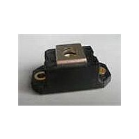
DIODE SCHOTTKY 45V 120A HALF-PAK
Manufacturer
Vishay
Specifications of 120NQ045R
Voltage - Forward (vf) (max) @ If
570mV @ 120A
Current - Reverse Leakage @ Vr
10mA @ 45V
Current - Average Rectified (io) (per Diode)
120A
Voltage - Dc Reverse (vr) (max)
45V
Diode Type
Schottky
Speed
Fast Recovery =< 500ns, > 200mA (Io)
Diode Configuration
Single
Mounting Type
Chassis Mount
Package / Case
D-67 HALF-PAK
Product
Schottky Rectifiers
Peak Reverse Voltage
45 V
Forward Continuous Current
120 A
Max Surge Current
29000 A
Configuration
Single
Forward Voltage Drop
0.73 V at 240 A
Maximum Reverse Leakage Current
10000 uA
Operating Temperature Range
- 55 C to + 150 C
Mounting Style
Screw
Lead Free Status / RoHS Status
Lead free / RoHS Compliant
Reverse Recovery Time (trr)
-
Lead Free Status / RoHS Status
Lead free / RoHS Compliant, Lead free / RoHS Compliant
Other names
*120NQ045R
VS-120NQ045R
VS-120NQ045R
VS120NQ045R
VS120NQ045R
VS-120NQ045R
VS-120NQ045R
VS120NQ045R
VS120NQ045R
Available stocks
Company
Part Number
Manufacturer
Quantity
Price

Part Number:
120NQ045R
Quantity:
91


120NQ...(R) Series
PD-2.224 rev. C 09/98
Electrical Specifications
2
Voltage Ratings
Absolute Maximum Ratings
Thermal-Mechanical Specifications
V
I
V
r
C
L
dv/dt Max. Voltage Rate of Change
T
T
R
R
wt
T
V
V
I
I
E
I
FSM
AR
RM
F(AV)
t
S
AS
FM
F(TO)
T
J
stg
R
RWM
thJC
thCS
Part number
Max. DC Reverse Voltage (V)
Max. Working Peak Reverse Voltage (V)
Parameters
Max. Average Forward Current
* See Fig. 5
Max. Peak One Cycle Non-Repetitive
Surge Current * See Fig. 7
Non-Repetitive Avalanche Energy
Repetitive Avalanche Current
Parameters
Max. Forward Voltage Drop
* See Fig. 1
Max. Reverse Leakage Current (1)
* See Fig. 2
Threshold Voltage
Forward Slope Resistance
Max. Junction Capacitance
Typical Series Inductance
(Rated V
Parameters
Max. Junction Temperature Range
Max. Storage Temperature Range
Max. Thermal Resistance Junction
to Case
Typical Thermal Resistance, Case to
Heatsink
Approximate Weight
Mounting Torque
Terminal Torque
Case Style
R
)
Max.
Min.
Max.
Min.
(1)
-55 to 150
120NQ Units
120NQ Units
120NQ Units
-55 to 150
25.6 (0.9) g (oz.)
HALF PAK Module
10,000
23 (20)
29,000
17 (15)
29 (25)
46 (40)
5200
1550
0.57
0.73
0.52
0.69
0.32
1.37
0.40
0.15
500
120
7.0
10
81
12
Kg-cm
(Ibf-in)
V/ µs
°C/W
°C/W
120NQ035(R)
m
mA
mA
mJ
nH
pF
°C
°C
A
V
V
V
V
V
A
A
5µs Sine or 3µs Rect. pulse
10ms Sine or 6ms Rect. pulse
T
Frequency limited by T
DC operation
Mounting surface , smooth and greased
Non-lubricated threads
35
50% duty cycle @ T
Current decaying linearly to zero in 1 µsec
@ 120A
@ 240A
@ 120A
@ 240A
T
T
T
V
From top of terminal hole to mounting plane
J
J
J
J
R
= 25 °C, I
= 25 °C
= 125 °C
= T
= 5V
J
max.
DC
, (test signal range 100Khz to 1Mhz) 25 °C
AS
Conditions
= 12 Amps, L = 1.12 mH
Conditions
Conditions
120NQ040(R)
* See Fig. 4
(1) Pulse Width < 300µs, Duty Cycle < 2%
T
T
V
C
J
J
R
= 106° C, rectangular wave form
= 25 °C
= 125 °C
= rated V
40
J
max. V
R
A
= 1.5 x V
Following any rated
load condition and
with rated V
120NQ045(R)
R
www.irf.com
typical
45
RRM
applied
Related parts for 120NQ045R
Image
Part Number
Description
Manufacturer
Datasheet
Request
R

Part Number:
Description:
DIODE, SCHOTTKY RECTIFIER; DO-204AL (DO-41); 2A IF; 0.53 V (TYP.); 60V; 120PF
Manufacturer:
Vishay PCS
Datasheet:

Part Number:
Description:
357-036-542-201 CARDEDGE 36POS DL .156 BLK LOPRO
Manufacturer:
Vishay
Datasheet:
Part Number:
Description:
357-036-542-201 CARDEDGE 36POS DL .156 BLK LOPRO
Manufacturer:
Vishay
Datasheet:
Part Number:
Description:
357-036-542-201 CARDEDGE 36POS DL .156 BLK LOPRO
Manufacturer:
Vishay
Datasheet:
Part Number:
Description:
357-036-542-201 CARDEDGE 36POS DL .156 BLK LOPRO
Manufacturer:
Vishay
Datasheet:
Part Number:
Description:
357-036-542-201 CARDEDGE 36POS DL .156 BLK LOPRO
Manufacturer:
Vishay
Datasheet:
Part Number:
Description:
357-036-542-201 CARDEDGE 36POS DL .156 BLK LOPRO
Manufacturer:
Vishay
Datasheet:
Part Number:
Description:
357-036-542-201 CARDEDGE 36POS DL .156 BLK LOPRO
Manufacturer:
Vishay
Datasheet:
Part Number:
Description:
357-036-542-201 CARDEDGE 36POS DL .156 BLK LOPRO
Manufacturer:
Vishay
Datasheet:
Part Number:
Description:
357-036-542-201 CARDEDGE 36POS DL .156 BLK LOPRO
Manufacturer:
Vishay
Datasheet:
Part Number:
Description:
357-036-542-201 CARDEDGE 36POS DL .156 BLK LOPRO
Manufacturer:
Vishay
Datasheet:
Part Number:
Description:
357-036-542-201 CARDEDGE 36POS DL .156 BLK LOPRO
Manufacturer:
Vishay
Datasheet:
Part Number:
Description:
357-036-542-201 CARDEDGE 36POS DL .156 BLK LOPRO
Manufacturer:
Vishay
Datasheet:
Part Number:
Description:
357-036-542-201 CARDEDGE 36POS DL .156 BLK LOPRO
Manufacturer:
Vishay
Datasheet:
Part Number:
Description:
357-036-542-201 CARDEDGE 36POS DL .156 BLK LOPRO
Manufacturer:
Vishay
Datasheet: