CM75DU-24H Powerex Inc, CM75DU-24H Datasheet - Page 3
CM75DU-24H
Manufacturer Part Number
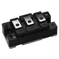
CM75DU-24H
Description
IGBT MOD DUAL 1200V 75A U SER
Manufacturer
Powerex Inc
Series
IGBTMOD™r
Specifications of CM75DU-24H
Package / Case
Module
Configuration
Half Bridge
Voltage - Collector Emitter Breakdown (max)
1200V
Vce(on) (max) @ Vge, Ic
3.7V @ 15V, 75A
Current - Collector (ic) (max)
75A
Current - Collector Cutoff (max)
1mA
Input Capacitance (cies) @ Vce
11nF @ 10V
Power - Max
600W
Input
Standard
Ntc Thermistor
No
Mounting Type
Chassis Mount
Dc Collector Current
75A
Collector Emitter Voltage Vces
1.2kV
Power Dissipation Pd
450W
Collector Emitter Voltage V(br)ceo
1.2kV
Operating Temperature Range
-40°C To +150°C
Lead Free Status / RoHS Status
Lead free / RoHS Compliant
Igbt Type
-
Lead Free Status / RoHS Status
Lead free / RoHS Compliant, Lead free / RoHS Compliant
Available stocks
Company
Part Number
Manufacturer
Quantity
Price
Company:

Part Number:
CM75DU-24H
Manufacturer:
MITSUBISHI
Quantity:
26
Company:
Part Number:
CM75DU-24H
Manufacturer:
MITS
Quantity:
1 000
Part Number:
CM75DU-24H
Manufacturer:
MITSUBISHI/三菱
Quantity:
20 000
Part Number:
CM75DU-24H
Quantity:
55


Powerex, Inc., 200 E. Hillis Street, Youngwood, Pennsylvania 15697-1800 (724) 925-7272
CM75DU-24F
Trench Gate Design Dual IGBTMOD™
75 Amperes/1200 Volts
Dynamic Electrical Characteristics,T j = 25°C unless otherwise specified
Characteristics
Input Capacitance
Output Capacitance
Reverse Transfer Capacitance
Inductive
Load
Switch
Times
Diode Reverse Recovery Time**
Diode Reverse Recovery Charge**
Thermal and Mechanical Characteristics, T j = 25°C unless otherwise specified
Characteristics
Thermal Resistance, Junction to Case
Thermal Resistance, Junction to Case
Thermal Resistance, Junction to Case
Contact Thermal Resistance
** Represents characteristics of the anti-parallel, emitter-to-collector free-wheel diode (FWDi).
Turn-on Delay Time
Rise Time
Turn-off Delay Time
Fall Time
R th(j-c) 'Q
R th(j-c) Q
R th(j-c) D
R th(c-f)
Symbol
Symbol
t d(on)
t d(off)
C oes
C res
C ies
Q rr
t rr
t r
t f
Per Module, Thermal Grease Applied
Per FWDi 1/2 Module, T c Reference
Per IGBT 1/2 Module, T c Reference
T c Reference Point Under Chip
Point per Outline Drawing
Point per Outline Drawing
V CC = 600V, I C = 75A,
V CE = 10V, V GE = 0V
Per IGBT 1/2 Module,
V GE1 = V GE2 = 15V,
Switching Operation
Inductive Load
Test Conditions
Test Conditions
R G = 4.2,
I E = 75A
Min.
Min.
–
–
–
–
–
–
–
–
–
–
–
–
–
Typ.
Typ.
–
–
–
–
–
–
–
–
3.1
–
0.19
0.045
100
400
300
150
29
50
Max.
Max.
1.3
0.75
–
0.28
0.47
–
Units
Units
°C/W
°C/W
°C/W
°C/W
μC
ns
ns
ns
ns
ns
nf
nf
nf
3
Related parts for CM75DU-24H
Image
Part Number
Description
Manufacturer
Datasheet
Request
R

Part Number:
Description:
IGBT MOD DUAL 600V 75A F SER
Manufacturer:
Powerex Inc
Datasheet:

Part Number:
Description:
IGBT MOD DUAL 600V 75A U SER
Manufacturer:
Powerex Inc
Datasheet:
Part Number:
Description:
IGBT MOD DUAL 1200V 75A F SER
Manufacturer:
Powerex Inc
Datasheet:
Part Number:
Description:
Manufacturer:
Powerex Inc
Datasheet:
Part Number:
Description:
Manufacturer:
Powerex Inc
Datasheet:
Part Number:
Description:
Manufacturer:
Powerex Inc
Datasheet:
Part Number:
Description:
Manufacturer:
Powerex Inc
Datasheet:
Part Number:
Description:
Manufacturer:
Powerex Inc
Datasheet:
Part Number:
Description:
Manufacturer:
Powerex Inc
Datasheet:
Part Number:
Description:
Manufacturer:
Powerex Inc
Datasheet:
Part Number:
Description:
Manufacturer:
Powerex Inc
Datasheet:
Part Number:
Description:
Manufacturer:
Powerex Inc
Datasheet:
Part Number:
Description:
Manufacturer:
Powerex Inc
Datasheet:
Part Number:
Description:
Manufacturer:
Powerex Inc
Datasheet: