CM400HA-12H Powerex Inc, CM400HA-12H Datasheet - Page 2
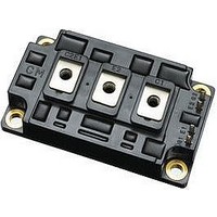
CM400HA-12H
Manufacturer Part Number
CM400HA-12H
Description
IGBT MOD SGL 600V 400A H SER
Manufacturer
Powerex Inc
Series
IGBTMOD™r
Datasheet
1.CM400HA-12H.pdf
(4 pages)
Specifications of CM400HA-12H
Configuration
Single
Voltage - Collector Emitter Breakdown (max)
600V
Vce(on) (max) @ Vge, Ic
2.8V @ 15V, 400A
Current - Collector (ic) (max)
400A
Current - Collector Cutoff (max)
1mA
Input Capacitance (cies) @ Vce
40nF @ 10V
Power - Max
1500W
Input
Standard
Ntc Thermistor
No
Mounting Type
Chassis Mount
Package / Case
Module
Transistor Polarity
N Channel
Dc Collector Current
400A
Power Dissipation Pd
1.5kW
Collector Emitter Voltage V(br)ceo
2.8V
Continuous Collector Current Ic
400A
Collector Emitter Saturation Voltage Vce(sat)
2.1V
Lead Free Status / RoHS Status
Contains lead / RoHS non-compliant
Igbt Type
-
Lead Free Status / RoHS Status
Contains lead / RoHS non-compliant, Contains lead / RoHS non-compliant
Available stocks
Company
Part Number
Manufacturer
Quantity
Price
Company:

Part Number:
CM400HA-12H
Manufacturer:
MITSUBISHI
Quantity:
26
Company:
Part Number:
CM400HA-12H
Manufacturer:
MITSUBISHI
Quantity:
560
Part Number:
CM400HA-12H
Manufacturer:
MIT
Quantity:
20 000
Part Number:
CM400HA-12H
Quantity:
55


174
Powerex, Inc., 200 Hillis Street, Youngwood, Pennsylvania 15697-1800 (724) 925-7272
CM400HA-12H
Single IGBTMOD™ H-Series Module
400 Amperes/600 Volts
Absolute Maximum Ratings, T
Ratings
Junction Temperature
Storage Temperature
Collector-Emitter Voltage (G-E SHORT)
Gate-Emitter Voltage
Collector Current
Peak Collector Current
Diode Forward Current
Diode Forward Surge Current
Power Dissipation
Max. Mounting Torque M6 Terminal Screws
Max. Mounting Torque M6 Mounting Screws
Module Weight (Typical)
V Isolation
* Pulse width and repetition rate should be such that device junction temperature does not exceed the device rating.
Static Electrical Characteristics, T
Characteristics
Collector-Cutoff Current
Gate Leakage Current
Gate-Emitter Threshold Voltage
Collector-Emitter Saturation Voltage
Total Gate Charge
Diode Forward Voltage
** Pulse width and repetition rate should be such that device junction temperature rise is negligible.
Dynamic Electrical Characteristics, T
Characteristics
Input Capacitance
Output Capacitance
Reverse Transfer Capacitance
Resistive
Load
Switching
Times
Diode Reverse Recovery Time
Diode Reverse Recovery Charge
Thermal and Mechanical Characteristics, T
Characteristics
Thermal Resistance, Junction to Case
Thermal Resistance, Junction to Case
Contact Thermal Resistance
Turn-on Delay Time
Rise Time
Turn-off Delay Time
Fall Time
j
= 25 C unless otherwise specified
j
= 25 C unless otherwise specified
V
V
Symbol
Symbol
Symbol
R
R
R
CE(sat)
t
t
I
I
C
GE(th)
V
C
C
d(on)
d(off)
GES
th(c-f)
CES
Q
th(j-c)
th(j-c)
j
Q
t
oes
FM
t
ies
res
t
= 25 C unless otherwise specified
rr
r
f
G
rr
j
= 25 C unless otherwise specified
Per Module, Thermal Grease Applied
V
I
C
CC
V
V
I
I
GE1
= 400A, V
E
E
GE
= 400V, I
V
V
= 400A, di
= 400A, di
V
I
I
C
C
I
CC
CE
GE
= 0V, V
E
= V
= 40mA, V
= 400A, V
= 400A, V
Test Conditions
Test Conditions
Test Conditions
= V
= 300V, I
= V
GE2
Per FWDi
Per IGBT
GE
C
CES
GES
CE
= 400A, V
= 15V, R
E
E
= 15V, T
/dt = –800A/ s
/dt = –800A/ s
= 10V, f = MHz
, V
, V
GE
CE
C
GS
GE
CE
= 400A,
= 15V
= 10V
= 0V
= 0V
G
= 0V
j
GS
= 150 C
= 1.6
Symbol
V
V
V
T
I
I
= 15V
GES
RMS
CES
CM
P
I
FM
T
I
stg
–
–
–
C
F
d
j
Min.
Min.
Min.
4.5
–
–
–
–
–
–
–
–
–
–
–
–
–
–
–
–
–
–
CM400HA-12H
–40 to 150
–40 to 125
1500
2500
800*
800*
600
400
400
400
26
26
1200
20
2.15
1.08
Typ.
Typ.
Typ.
6.0
2.1
–
–
–
–
–
–
–
–
–
–
–
–
–
–
0.085
0.040
2.8**
Max.
Max.
Max.
0.18
350
600
350
300
110
1.0
0.5
7.5
2.8
–
40
14
–
–
8
Amperes
Amperes
Amperes
Amperes
Grams
Watts
Volts
Volts
Volts
Units
in-lb
in-lb
Volts
Volts
Volts
Volts
Units
Units
Units
C
C
C/W
C/W
C/W
mA
nC
nF
nF
nF
ns
ns
ns
ns
ns
C
A
Related parts for CM400HA-12H
Image
Part Number
Description
Manufacturer
Datasheet
Request
R

Part Number:
Description:
IGBT MOD SGL 1200V 400A H SER
Manufacturer:
Powerex Inc
Datasheet:

Part Number:
Description:
IGBT MOD SGL 1200V 400A A SERIES
Manufacturer:
Powerex Inc
Datasheet:
Part Number:
Description:
IGBT MOD SGL 1400V 400A H SER
Manufacturer:
Powerex Inc
Datasheet:

Part Number:
Description:
TRANSISTOR,IGBT POWER MODULE,INDEPENDENT,1.7kV V(BR)CES,400A I(C)
Manufacturer:
Powerex Inc
Datasheet:

Part Number:
Description:
T-3 1/4 Miniature Bayonet Base
Manufacturer:
CML [Chicago Miniature Lamp,inc]
Datasheet:
Part Number:
Description:
Silicon NPN high power VHF/UHF transistor
Manufacturer:
Great American Electronics
Part Number:
Description:
Manufacturer:
Powerex Inc
Datasheet:
Part Number:
Description:
Manufacturer:
Powerex Inc
Datasheet:
Part Number:
Description:
Manufacturer:
Powerex Inc
Datasheet:
Part Number:
Description:
Manufacturer:
Powerex Inc
Datasheet:
Part Number:
Description:
Manufacturer:
Powerex Inc
Datasheet:
Part Number:
Description:
Manufacturer:
Powerex Inc
Datasheet: