CM400DY-24A Powerex Inc, CM400DY-24A Datasheet - Page 3
CM400DY-24A
Manufacturer Part Number
CM400DY-24A
Description
IGBT MOD DUAL 1200V 400A A SER
Manufacturer
Powerex Inc
Series
IGBTMOD™r
Type
IGBT Moduler
Datasheet
1.CM400DY-24A.pdf
(4 pages)
Specifications of CM400DY-24A
Configuration
Half Bridge
Voltage - Collector Emitter Breakdown (max)
1200V
Vce(on) (max) @ Vge, Ic
3V @ 15V, 400A
Current - Collector (ic) (max)
400A
Current - Collector Cutoff (max)
1mA
Input Capacitance (cies) @ Vce
70nF @ 10V
Power - Max
2710W
Input
Standard
Ntc Thermistor
No
Mounting Type
Chassis Mount
Package / Case
Module
Transistor Polarity
N Channel
Dc Collector Current
400A
Collector Emitter Voltage Vces
1.2kV
Power Dissipation Pd
2.71kW
Collector Emitter Voltage V(br)ceo
1.2kV
Prx Availability
RequestQuote
Distributorinventory
View
Voltage
1200V
Current
400A
Circuit Configuration
Dual
Rohs Compliant
Yes
Recommended Gate Driver
VLA503
Recommended Dc To Dc Converter
VLA106-15242 or VLA106-24242
Interface Circuit Ref Design
BG2B-5015
Lead Free Status / RoHS Status
Lead free / RoHS Compliant
For Use With
BG2B-5015 - KIT DEV BOARD 2CN 5A FOR IGBTBG2B-3015 - KIT DEV BOARD 2CN 3A FOR IGBTBG2B-1515 - KIT DEV BOARD 1.5A FOR IGBTBG2A-NF - KIT DEV BOARD FOR IGBT
Igbt Type
-
Lead Free Status / RoHS Status
Lead free / RoHS Compliant, Lead free / RoHS Compliant
Other names
835-1018
Available stocks
Company
Part Number
Manufacturer
Quantity
Price
Company:

Part Number:
CM400DY-24A
Manufacturer:
MITSUBISHI
Quantity:
492
Part Number:
CM400DY-24A
Manufacturer:
MIT
Quantity:
20 000
Part Number:
CM400DY-24A
Quantity:
55


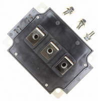
CM400DY-24A
Dual IGBTMOD™ A-Series Module
400 Amperes/1200 Volts
Thermal and Mechanical Characteristics, T
Characteristics
Thermal Resistance, Junction to Case*
Thermal Resistance, Junction to Case*
Contact Thermal Resistance
External Gate Resistance
*T
Rev. 10/07
Powerex, Inc., 173 Pavilion Lane, Youngwood, Pennsylvania 15697 (724) 925-7272
C
800
600
400
200
, T
10
10
10
0
3
2
1
f
measured point is just under the chips.
0
0
V
COLLECTOR-EMITTER VOLTAGE, V
EMITTER-COLLECTOR VOLTAGE, V
GE
20V
FORWARD CHARACTERISTICS
=
OUTPUT CHARACTERISTICS
1
2
FREE-WHEEL DIODE
15
13
(TYPICAL)
(TYPICAL)
2
4
6
3
T
T
CE
EC
j
j
T
= 25°C
= 125°C
, (VOLTS)
j
4
, (VOLTS)
8
= 25 °C
12
11
10
9
10
5
R
R
Symbol
R
th(j-c)
th(j-c)
th(c-f)
R
10
10
10
10
G
-1
0
4
3
2
1
2
1
0
10
Q
D
SATURATION VOLTAGE CHARACTERISTICS
0
-1
COLLECTOR-EMITTER VOLTAGE, V
V
V
j
GE
GE
COLLECTOR-CURRENT, I
= 25°C unless otherwise specified
Per 1/2 Module, Thermal Grease Applied
= 15V
= 0V
T
T
200
j
j
CAPACITANCE VS. V CE
COLLECTOR-EMITTER
= 25°C
= 125°C
10
0
(TYPICAL)
(TYPICAL)
Per FWDi 1/2 Module
Per IGBT 1/2 Module
400
Test Conditions
C
10
, (AMPERES)
1
600
C
C
C
CE
oes
res
ies
, (VOLTS)
800
10
2
10
10
10
10
8
6
4
2
0
3
2
1
10
SATURATION VOLTAGE CHARACTERISTICS
6
T
1
Min.
0.78
I
j
C
—
—
—
= 25°C
GATE-EMITTER VOLTAGE, V
= 160A
COLLECTOR CURRENT, I
SWITCHING CHARACTERISTICS
8
t
t
d(on)
d(off)
COLLECTOR-EMITTER
10
HALF-BRIDGE
0.02
Typ.
—
—
—
(TYPICAL)
(TYPICAL)
12
10
2
14
I
C
I
C
= 800A
C
= 400A
0.046
0.085
V
V
R
T
Inductive Load
Max.
, (AMPERES)
CC
GE
j
10
GE
G
—
16
= 125°C
= 0.78Ω
, (VOLTS)
= 600V
= 15V
t
t
18
r
f
°C/W
°C/W
°C/W
Units
10
20
Ω
3
3
Related parts for CM400DY-24A
Image
Part Number
Description
Manufacturer
Datasheet
Request
R

Part Number:
Description:
Manufacturer:
Powerex Inc
Datasheet:
Part Number:
Description:
Manufacturer:
Powerex Inc
Datasheet:

Part Number:
Description:
IGBT MOD DUAL 600V 400A H SER
Manufacturer:
Powerex Inc
Datasheet:

Part Number:
Description:
IGBT MOD DUAL 600V 400A NF SER
Manufacturer:
Powerex Inc
Datasheet:
Part Number:
Description:
IGBT MOD DUAL 1200V 400A NF SER
Manufacturer:
Powerex Inc
Datasheet:
Part Number:
Description:
IGBT MODULE A-SERIES DUAL DP 1700 400
Manufacturer:
Powerex Inc
Datasheet:

Part Number:
Description:
T-3 1/4 Miniature Bayonet Base
Manufacturer:
CML [Chicago Miniature Lamp,inc]
Datasheet:
Part Number:
Description:
Silicon NPN high power VHF/UHF transistor
Manufacturer:
Great American Electronics
Part Number:
Description:
Manufacturer:
Powerex Inc
Datasheet:
Part Number:
Description:
Manufacturer:
Powerex Inc
Datasheet:
Part Number:
Description:
Manufacturer:
Powerex Inc
Datasheet:
Part Number:
Description:
Manufacturer:
Powerex Inc
Datasheet: