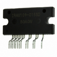
IRAM109-015SD International Rectifier, IRAM109-015SD Datasheet

IRAM109-015SD
Specifications of IRAM109-015SD
Related parts for IRAM109-015SD
IRAM109-015SD Summary of contents
Page 1
... Integrated Power Hybrid IC for Appliance Motor Drive Applications Description International Rectifier’s IRAM109-015SD is a multi-chip Hybrid IC developed for low power appliance motor control applications such as Fans, Pumps, refrigerator compressors, etc. The compact Single in line (SIP-S) package minimizes PCB space. Several built-in protection features such as temperature feedback, shoot through prevention, under voltage lockout, and shutdown input makes this a very robust solution ...
Page 2
... IRAM109-015SD Internal Electrical Schematic – IRAM109-015SD DB1 RG1 1 10 VCC RG2 5 6 Vss COM IC1 DB2 1 10 VCC VB RG3 RG4 5 6 Vss COM IC2 www.irf.com ...
Page 3
... SS V +0. 25°C Unless Otherwise Specified) J Min Typ Max 500 --- --- --- 2.2 2.7 --- 5.5 --- --- 10 100 --- 0.87 1.1 --- 0.70 --- --- --- 1.25 --- 22 --- --- --- ±5 IRAM109-015SD Units Conditions T = 25°C, I =1mA =100µs, T =100° Units Conditions V =5V, I =250µ =1A, V =15V =1A, V =15V, T =150° µA ...
Page 4
... IRAM109-015SD Recommended Operating Conditions The Input/Output logic timing diagram is shown in Figure 1. For proper operation the device should be used within the recommended conditions. All voltages are absolute referenced to COM. The V 15V differential. Symbol Definition + Positive Bus Input Voltage V V High side floating supply voltage ...
Page 5
... Resistance 125 B B-constant (25-50°C) Temperature Range Typ. Dissipation constant Input-Output Logic Level Table SD IN1 Off www.irf.com IRAM109-015SD Min Typ Max Units Conditions --- 5.1 6.9 °C/W Flat, Insulation Material Min Typ Max Units Conditions T = 25°C 97 100 103 125°C 2 ...
Page 6
... IRAM109-015SD Timing Parameter Definitions Figure 1. Input/Output Timing Diagram 50% 50 10% LO-HO LO 90% MDT LO-HO Figure 3. Deadtime Waveform Diagram 6 IN (LO) IN (HO Figure 2. Switching Time Waveform Diagram IN (LO) IN (HO) DT HO-LO 10% HO-LO Figure 4. Delay Matching Waveform Diagram 50% 50% t off 90% 90% 10% 10% 50 www.irf.com ...
Page 7
... Typical Application Connection – IRAM109-015SD Application Circuit Recommendation 1. Electrolytic bus capacitors should be mounted as close to the module bus terminals as possible to reduce ringing and EMI problems. Additional high frequency ceramic capacitor mounted close to the module pins will further improve performance order to provide good decoupling between VCC-VSS and PO1,2-VB1,2 terminals, and the capacitors shown connected between these terminals should be located very close to the module pins. Additional high frequency capacitors, typically 0.1µ ...
Page 8
... IRAM109-015SD Module Pin-Out Description Pin Name 1 IN1 2 IN2 SENSE - Description Logic Input Gate Driver - Phase 1 Logic Input Gate Driver - Phase 2 Temperature Feedback Shun-down Function +15V Main Supply Negative Main Supply Current Feedback Negative Bus Input Voltage none none Output 2 - High Side Floating Supply Offset Voltage ...
Page 9
... Figure 6. Maximum Sinusoidal Phase Current vs. Modulation Frequency Sinusoidal Modulation, V www.irf.com T = 80º 90º 100º PWM Sw itching Frequency - kHz + =360V, T =150°C, F =50Hz, MI=0.8, PF=0.6 J MOD 10 Modulation Frequency - Hz + =360V, T =150°C, MI=0.8, PF=0.6 J IRAM109-015SD T = 150ºC J Sinusoidal Modulation 12kHz PWM F = 16kHz PWM F = 20kHz PWM 100 9 ...
Page 10
... IRAM109-015SD 150ºC J Sinusoidal Modulation Figure 7. Total Power Losses vs. PWM Switching Frequency Sinusoidal Modulation 150º Sinusoidal Modulation 0.2 Figure 8. Total Power Losses vs. Output Phase Current Sinusoidal Modulation PWM Sw itching Frequency - kHz + =360V, T =150°C, MI=0.8, PF=0.6 J 0.4 0.6 0.8 1 Output Phase Current - A ...
Page 11
... Internal Therm istor Tem perature Equivalent Read Out - °C Figure 10. Estimated Maximum MOSFET Junction Temperature vs. Thermistor Temperature www.irf.com F = 12kHz PWM F = 16kHz PWM F = 20kHz PWM 0.4 0.6 0.8 1 Output Phase Current - A RMS + =360V, T =150°C, Modulation Depth=0.8, PF=0 3.09 T herm 100 IRAM109-015SD 1.2 1.4 1.6 115.8 105 110 115 120 11 ...
Page 12
... IRAM109-015SD 5.0 4.5 4 THERM THERM THERM 3.5 °C °C -40 4397119 25 3.0 -35 3088599 30 -30 2197225 35 2.5 -25 1581881 40 -20 1151037 45 -15 846579 50 2.0 -10 628988 55 1.5 -5 471632 60 0 357012 65 5 272500 70 1.0 10 209710 75 15 162651 80 0.5 20 127080 85 0.0 -40 -30 -20 -10 0 Figure 11. Thermistor Readout vs. Temperature (12Kohm pull-up resistor, 5V) and Normal Thermistor Resistance values vs ...
Page 13
... Figure 13. Switching Parameter Definitions V DS 50% 90 IN1/IN2 10 Figure 13a. Input to Output propagation turn-on delay time. Figure 13c. Diode Reverse Recovery. www.irf.com 50% 50% V IN1/IN2 DS IN1/IN2 50 OFF Figure 13b. Input to Output propagation turn-off IRAM109-015SD IN1 / IN2 10 delay time. 13 ...
Page 14
... IRAM109-015SD Figure CT1. Switching Loss Circuit 14 www.irf.com ...
Page 15
... Package Outline IRAM109-015SD note3 IRAM109-015SD note2 For mounting instruction see AN-1049 IR WORLD HEADQUARTERS: 233 Kansas St., El Segundo, California 90245, USA Tel: (310) 252-7105 www.irf.com IRAM109-015SD missing pin ; 9,10,13,14,17,18 note4 note1: Unit Tolerance is +0.4mm, Unless Otherwise Specified. note2: Mirror Surface Mark indicates Pin1 Identification. ...


