IRAMS06UP60A-2 International Rectifier, IRAMS06UP60A-2 Datasheet
IRAMS06UP60A-2
Specifications of IRAMS06UP60A-2
Available stocks


Related parts for IRAMS06UP60A-2

IRAMS06UP60A-2 Summary of contents
Page 1
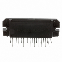
... International Rectifier’s IRAMS06UP60A is an Integrated Power Module developed and optimized for electronic motor control in appliance applications specifically for VF compressor drives for refrigerators and freezer or in heating and ventilation as electronic fan controls. The IRAMS06UP60A offers an extremely compact, high performance AC motor-driver in a single isolated package for a very simple design. ...
Page 2
... IRAMS06UP60A Internal Electrical Schematic - IRAMS06UP60A V (10) + VRU (12) VRV (13) VRW (14) Rg1 VB1 (7) U, VS1 (8) VB2 (4) V, VS2 (5) VB3 (1) W, VS3 ( HIN1 (15) HIN2 (16) HIN3 (17) LIN1 (18) LIN2 (19) LIN3 (20) T/I (21) TRIP R THERMISTOR T VDD (22) VSS (23) 2 Rg3 Rg5 VS1 LO1 16 VB2 HO2 VS2 VB3 HO3 VS3 ...
Page 3
... Thermal Resistance Symbol Parameter Junction to case thermal R resistance, each IGBT under th(J-C) inverter operation. Junction to case thermal R resistance, each Diode under th(J-C) inverter operation. Thermal Resistance case to R th(C-S) sink www.irf.com IRAMS06UP60A = 25°C J Min Typ Max Units Conditions 600 --- --- --- 0.3 --- V/° ...
Page 4
... IRAMS06UP60A Absolute Maximum Ratings Driver Function Absolute Maximum Ratings indicate substaines limits beyond which damage to the device may occur. All voltage pa- rameters are absolute voltages referenced to Symbol Definition V High Side offset voltage S1,2,3 V High Side floating supply voltage B1,2,3 V Low Side and logic fixed supply voltage ...
Page 5
... B-constant (25-50°C) Temperature Range Typ. Dissipation constant Note 1: For more details, see IR21365 data sheet Note 2: Logic operational for V from V s DT97-3 for more details) Thermistor Built-in IRAMS06UP60A V T/I TRIP 6.8k Note 3: The Maximum recommended sense voltage at the T/I www.irf.com =2kHz, V ...
Page 6
... IRAMS06UP60A HIN1,2,3 LIN1,2,3 HO1,2,3 LO1,2,3 Itrip U,V,W Figure1. Input/Output Timing Diagram Note 5: The shaded area indicates that both high-side and low-side switches are off and therefore the half-bridge output voltage would be determined by the direction of current flow in the load. Ho Hin1,2,3 (15,16,17) IC Driver ...
Page 7
... HIN1,2,3 LIN1,2,3 T/Itrip U,V,W Figure 2. I Timing Waveform Trip Note 6: The shaded area indicates that both high-side and low-side switches are off and therefore the half-bridge output voltage would be determined by the direction of current flow in the load. www.irf.com IRAMS06UP60A 50% 50% tfltclr 7 ...
Page 8
... IRAMS06UP60A Module Pin-Out Description Pin Name 1 VB3 2 W,VS3 VB2 5 V,VS2 VB1 8 U,VS1 LE1 13 LE2 14 LE3 15 HIN1 16 HIN2 17 HIN3 18 LIN1 19 LIN2 20 LIN3 21 T/Itrip 22 VCC 23 VSS 8 Description High Side Floating Supply Voltage 3 Output 3 - High Side Floating Supply Offset Voltage none High Side Floating Supply voltage 2 ...
Page 9
... Typical Application Connection IRAMS06UP60A U 3-ph AC MOTOR CURRENT SENSING CAN USE A W SINGLE SENSE RESISTOR OR PHASE LEG SENSING AS SHOWN DC BUS CAPACITORS PHASE LEG CURRENT SENSE CONTROLLER 5k TEMP 6.8K SENSE 1m 3.3 V O/C SENSE (ACTIVE LOW) 1. Electrolytic bus capacitors should be mounted as close to the module bus terminals as possible to reduce ringing and EMI problems ...
Page 10
... IRAMS06UP60A 5.0 4.5 4.0 3.5 3.0 2.5 2.0 1.5 1.0 0.5 0 Figure 3. Maximum sinusoidal phase current as function of switching frequency V+=400V, T =150°C, Modulation Depth=0.8, PF=0.6 j 4.0 12 kHz 3.5 16 kHz 3.0 20 kHz 2.5 2.0 1.5 1.0 0.5 0.0 1 Figure 4. Maximum sinusoidal phase current as function of modulation frequency V+=400V, T =150° ...
Page 11
... Figure 5. IGBT Turn-on. Typical turn-on waveform @T 4.5 4 3.5 3 2.5 2 1.5 1 0.5 0 -0.5 0.000 0.100 0.200 0.300 Figure 6. IGBT Turn-off. Typical turn-off waveform @T www.irf.com IRAMS06UP60A 0.400 0.500 0.600 0.700 Time ( s) =125°C, V+=400V j Current Voltage 0.400 0.500 0.600 0.700 Time ( s) =125°C, V+=400V j 450 ...
Page 12
... IRAMS06UP60A 1000 100 Figure 7. Variation of thermistor resistance with temperature Temperature (°C) Maximum Nominal Minimum 100 120 140 www.irf.com ...
Page 13
... Figure 8. Estimated maximum IGBT junction temperature with thermistor tempera- ture 20 17 12.5 10 7.5 6.8 4.7 5 3.3 2.5 2 Figure 9. Recommended minimum Bootstrap Capacitor value Vs Switching Frequency www.irf.com Vbus=400V Imot=3Arms fsw=20kHz 80 90 100 Thermistor temperature (°C) 1.5 10 Frequency (kHz) IRAMS06UP60A 110 120 ...
Page 14
... IRAMS06UP60A Figure 11. Switching Parameter Definitions V CE 50 Figure 11a. Input to Output propagation turn-on delay time Figure 11c. Diode Reverse Recovery 50 10 OFF Figure 11b. Input to Output propagation turn-off delay time 90 10 www.irf.com ...
Page 15
... Driver Lo Lin1,2,3 Figure CT1. Switching Loss Circuit Hin1,2,3 1k 10k Driver Lin1,2,3 5VZD IN Figure CT2. S.C.SOA Circuit Hin1,2,3 1k 10k Driver 5VZD Lin1,2,3 IN Figure CT3. R.B.SOA Circuit www.irf.com V+ U,V U,V U,V IRAMS06UP60A IN PWM =Peak Voltage on the IGBT die =Peak Voltage on the IGBT die ...
Page 16
... IRAMS06UP60A Package Outline 027-E2D24 IRAMS06UP60A note 1 Standard pin leadforming option Notes: Dimensions Marking for pin 1 identification 2- Product Part Number 3- Lot and Date code marking For mounting instruction, see AN1049 1 6 note 3 note 2 www.irf.com ...
Page 17
... Package Outline note 2 027-E2D24 IRAMS06UP60A-2 note 1 Pin leadforming option -2 Notes: Dimensions Marking for pin 1 identification 2- Product Part Number 3- Lot and Date code marking IR WORLD HEADQUARTERS: 233 Kansas St., El Segundo, California 90245, USA Tel: (310) 252-7105 www.irf.com IRAMS06UP60A note 3 Data and Specifications are subject to change without notice Visit us at www ...
Page 18
...