IRAMS10UP60B-2 International Rectifier, IRAMS10UP60B-2 Datasheet - Page 4
IRAMS10UP60B-2
Manufacturer Part Number
IRAMS10UP60B-2
Description
IC PWR MOD PLUG-N-DRIVE 600V 10A
Manufacturer
International Rectifier
Series
iMOTION™r
Type
IGBTr
Datasheet
1.IRAMS10UP60B-2.pdf
(17 pages)
Specifications of IRAMS10UP60B-2
Configuration
3 Phase
Current
10A
Voltage
600V
Voltage - Isolation
2000Vrms
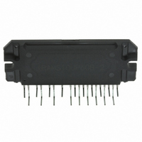
Package / Case
PCB Module
Lead Free Status / RoHS Status
Lead free / RoHS Compliant
Available stocks
Company
Part Number
Manufacturer
Quantity
Price
Company:

Part Number:
IRAMS10UP60B-2
Manufacturer:
ST
Quantity:
1 001
Company:
Part Number:
IRAMS10UP60B-2
Manufacturer:
IR
Quantity:
5 510


IRAMS10UP60B
Symbol
E
E
E
E
t
E
E
E
E
t
Q
RBSOA
SCSOA
I
The Input/Output logic timing diagram is shown in Figure 1. For proper operation the device should be used within the
recommende conditions. All voltages are absolute referenced to COM/I
at 15V differential (Note 3)
V
V
V
V
V
V
Note 3: For more details, see IR21363 data sheet
Note 4: Logic operational for V
(please refer to DT97-3 for more details)
Inverter Section Switching Characteristics @ T
Recommended Operating Conditions Driver Function
Symbol
RR
RR
CSC
ON
OFF
TOT
REC
ON
OFF
TOT
REC
B1,2,3
S1,2,3
CC
ITRIP
IN
EN
G
4
Turn-On Switching Loss
Turn-Off Switching Loss
Total Switching Loss
Diode Reverse Recovery energy
Diode Reverse Recovery time
Turn-On Switching Loss
Turn-off Switching Loss
Total Switching Loss
Diode Reverse Recovery energy
Diode Reverse Recovery time
Turn-On IGBT Gate Charge
Reverse Bias Safe Operating Area
Short Circuit Safe Operating Area
Short Circuit Collector Current
Parameter
High side floating supply voltage
High side floating supply offset voltage
Low side and logic fixed supply voltage
I
Logic input voltage LIN, HIN
Logic input voltage EN
Definition
TRIP
input voltage
s
from COM-5V to COM+600V. Logic state held for V
Min
---
---
---
---
---
---
---
---
---
---
---
10
---
FULL SQUARE
Typ
200
275
300
135
435
100
75
15
70
30
29
---
47
TRIP
Max
235
100
335
100
360
165
525
145
25
40
44
---
---
J
. The V
= 25°C
Units
S
nC
µJ
ns
µJ
ns
µs
A
offset is tested with all supplies biased
s
from COM-5V to COM-V
Note 4
V
Conditions
I
V
Energy losses include "tail" and
diode reverse recovery
I
V
Energy losses include "tail" and
diode reverse recovery
I
T
V
V
T
V
V
T
V
V
C
C
C
Min
S
CC
CC
J
+
CC
J
+
CC
J
+
CC
V
V
V
=5A, V
=5A, V
=15A, V
12
=150°C, I
=150°C, V
=150°C, V
+12
= 450V
= 360V,
= 360V, V
SS
SS
SS
=15V, L=2mH
=15V, L=2mH, T
=+15V to 0V
=+15V to 0V
=+15V to 0V
+
+
=400V
=400V
+
=400V, V
C
P
P
GE
=5A, V
V
=600V,
=600V, t
V
V
V
Max
=15V
S
450
SS
SS
SS
20
+20
+5
+5
+5
www.irf.com
P
J
GE
=150°C
=600V
BS
SC
=15V
.
See CT3
See CT2
<10µs
See CT2
See CT1
See CT1
Units
V
V
V
V
Related parts for IRAMS10UP60B-2
Image
Part Number
Description
Manufacturer
Datasheet
Request
R

Part Number:
Description:
SCHOTTKY RECTIFIER
Manufacturer:
International Rectifier Corp.
Datasheet:
Part Number:
Description:
SCHOTTKY RECTIFIER
Manufacturer:
International Rectifier Corp.
Datasheet:
Part Number:
Description:
SCHOTTKY RECTIFIER
Manufacturer:
International Rectifier Corp.
Datasheet:
Part Number:
Description:
SCHOTTKY RECTIFIER
Manufacturer:
International Rectifier Corp.
Datasheet:
Part Number:
Description:
SCHOTTKY RECTIFIER
Manufacturer:
International Rectifier Corp.
Datasheet:
Part Number:
Description:
SCHOTTKY RECTIFIER
Manufacturer:
International Rectifier Corp.
Datasheet:
Part Number:
Description:
SCHOTTKY RECTIFIER
Manufacturer:
International Rectifier Corp.
Datasheet:
Part Number:
Description:
SCHOTTKY RECTIFIER
Manufacturer:
International Rectifier Corp.
Datasheet:
Part Number:
Description:
SCHOTTKY RECTIFIER
Manufacturer:
International Rectifier Corp.
Datasheet:
Part Number:
Description:
SCHOTTKY RECTIFIER
Manufacturer:
International Rectifier Corp.
Datasheet:
Part Number:
Description:
SCHOTTKY RECTIFIER
Manufacturer:
International Rectifier Corp.
Datasheet:
Part Number:
Description:
SCHOTTKY RECTIFIER
Manufacturer:
International Rectifier Corp.
Datasheet:
Part Number:
Description:
SCHOTTKY RECTIFIER
Manufacturer:
International Rectifier Corp.
Datasheet:
Part Number:
Description:
SCHOTTKY RECTIFIER
Manufacturer:
International Rectifier Corp.
Datasheet:
Part Number:
Description:
SCHOTTKY RECTIFIER
Manufacturer:
International Rectifier Corp.
Datasheet: