PS21265-AP Powerex Inc, PS21265-AP Datasheet - Page 2
PS21265-AP
Manufacturer Part Number
PS21265-AP
Description
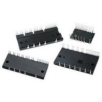
MOD IPM 600V 20A DIP
Manufacturer
Powerex Inc
Series
Intellimod™r
Type
IGBTr
Datasheet
1.PS21265-AP.pdf
(8 pages)
Specifications of PS21265-AP
Configuration
3 Phase
Current
20A
Voltage
600V
Voltage - Isolation
2500VDC
Package / Case
PCB Module
Dc Collector Current
20A
Collector Emitter Voltage Vces
600V
Power Dissipation Pd
51.2W
Collector Emitter Voltage V(br)ceo
600V
Operating Temperature Range
-20°C To +100°C
No. Of Pins
26
Rohs Compliant
Yes
Lead Free Status / RoHS Status
Lead free / RoHS Compliant
Available stocks
Company
Part Number
Manufacturer
Quantity
Price
Company:

Part Number:
PS21265-AP
Manufacturer:
MITSUBISHI
Quantity:
50
Company:
Part Number:
PS21265-AP
Manufacturer:
MITSUBISHI
Quantity:
300


2
Powerex, Inc., 173 Pavilion Lane, Youngwood, Pennsylvania 15697 (724) 925-7272 www.pwrx.com
PS21265-P / PS21265-AP
Intellimod™ Module
Dual-In-Line Intelligent Power Module
20 Amperes/600 Volts
Absolute Maximum Ratings, T
Characteristics
Power Device Junction Temperature*
Module Case Operation Temperature (See T
Storage Temperature
Mounting Torque, M4 Mounting Screws
Module Weight (Typical)
Self-protection Supply Voltage Limit (Short Circuit Protection Capability)**
Isolation Voltage, AC 1 minute, 60Hz Sinusoidal, Connection Pins to Heatsink Plate
*The maximum junction temperature rating of the power chips integrated within the DIP-IPM is 150°C (@T
**V
IGBT Inverter Sector
Collector-Emitter Voltage (T
Collector Current (T
Peak Collector Current (T
Supply Voltage (Applied between P - N)
Supply Voltage, Surge (Applied between P - N)
Collector Dissipation (T
Control Sector
Supply Voltage (Applied between V
Supply Voltage (Applied between V
Input Voltage (Applied between U
Fault Output Supply Voltage (Applied between F
Fault Output Current (Sink Current at F
Current Sensing Input Voltage (Applied between C
the average junction temperature should be limited to T
D
= 13.5 ~ 16.5V, Inverter Part, T
C
= 25°C)
C
C
= 25°C, per 1 Chip)
j
C
= 25°C, <1ms)
= 125°C, Non-repetitive, Less than 2µs
= 25°C)
P
, V
P1
UFB
P
-V
, W
O
-V
PC
j
Terminal)
= 25°C unless otherwise specified
UFS
P
j(avg)
, V
-V
C
PC
N1
, V
Measurement Point Illustration)
≤ 125°C (@T
-V
, U
VFB
O
NC
-V
IN
N
NC
-V
, V
-V
)
VFS
N
)
NC
, W
C
)
≤ 100°C).
, V
N
WFB
-V
NC
-V
)
WFS
)
C
≤ 100°C). However, to ensure safe operation of the DIP-IPM,
V
V
CC(surge)
CC(prot.)
Symbol
V
V
±I
V
V
V
V
T
V
±I
I
T
P
V
CES
—
—
FO
T
ISO
CC
stg
DB
FO
SC
CP
IN
C
C
D
C
j
PS21265-P / PS21265-AP
-0.5 ~ V
-0.5 ~ V
-0.5 ~ V
-20 to 125
-20 to 100
-40 to 125
2500
51.2
400
600
450
500
13
54
20
40
20
20
1
D
D
D
+0.5
+0.5
+0.5
08/10 Rev. 01
Amperes
Amperes
Grams
Watts
Units
Volts
Volts
Volts
Volts
Volts
Volts
Volts
Volts
Volts
Volts
in-lb
mA
°C
°C
°C
Related parts for PS21265-AP
Image
Part Number
Description
Manufacturer
Datasheet
Request
R


Part Number:
Description:
Manufacturer:
Powerex Inc
Datasheet:
Part Number:
Description:
Manufacturer:
Powerex Inc
Datasheet:
Part Number:
Description:
Manufacturer:
Powerex Inc
Datasheet:
Part Number:
Description:
Manufacturer:
Powerex Inc
Datasheet:
Part Number:
Description:
Manufacturer:
Powerex Inc
Datasheet:
Part Number:
Description:
Manufacturer:
Powerex Inc
Datasheet:
Part Number:
Description:
Manufacturer:
Powerex Inc
Datasheet:
Part Number:
Description:
Manufacturer:
Powerex Inc
Datasheet:
Part Number:
Description:
Manufacturer:
Powerex Inc
Datasheet:
Part Number:
Description:
Manufacturer:
Powerex Inc
Datasheet:
Part Number:
Description:
Manufacturer:
Powerex Inc
Datasheet:
Part Number:
Description:
Manufacturer:
Powerex Inc
Datasheet:
Part Number:
Description:
Manufacturer:
Powerex Inc
Datasheet: