PM400HSA120 Powerex Inc, PM400HSA120 Datasheet - Page 2
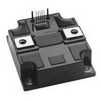
PM400HSA120
Manufacturer Part Number
PM400HSA120
Description
MOD IPM SGL 1200V 400A
Manufacturer
Powerex Inc
Series
Intellimod™r
Type
IGBTr
Datasheet
1.PM400HSA120.pdf
(4 pages)
Specifications of PM400HSA120
Configuration
Half Phase Inverter
Current
400A
Voltage
1200V
Voltage - Isolation
2500Vrms
Package / Case
Module
Transistor Polarity
N Channel
Dc Collector Current
400A
Collector Emitter Voltage Vces
1.2kV
Power Dissipation Pd
2.318kW
Collector Emitter Voltage V(br)ceo
1.2kV
Lead Free Status / RoHS Status
Contains lead / RoHS non-compliant
Available stocks
Company
Part Number
Manufacturer
Quantity
Price

Part Number:
PM400HSA120
Manufacturer:
MOSFET
Quantity:
20 000
Part Number:
PM400HSA120
Quantity:
60


680
Powerex, Inc., 200 Hillis Street, Youngwood, Pennsylvania 15697-1800 (724) 925-7272
PM400HSA120
Intellimod™ Module
Half Phase IGBT Inverter Output
400 Amperes/1200 Volts
Absolute Maximum Ratings, T
Characteristics
Power Device Junction Temperature
Storage Temperature
Case Operating Temperature
Mounting Torque, M6 Mounting Screws
Mounting Torque, M8 Main Terminal Screws
Module Weight (Typical)
Supply Voltage Protected by OC and SC (V
Isolation Voltage, AC 1 minute, 60Hz Sinusoidal
Control Sector
Supply Voltage Applied between (V
Input Voltage Applied between (C
Fault Output Supply Voltage (Applied between F
Fault Output Current
IGBT Inverter Sector
Collector-Emitter Voltage (V
Collector Current,
Peak Collector Current,
Collector Dissipation
Electrical and Mechanical Characteristics, T
Characteristics
Control Sector
Over Current Trip Level Inverter Part
Short Circuit Trip Level Inverter Part
Over Current Delay Time
Over Temperature Protection
Supply Circuit Under Voltage Protection
Supply Voltage
Circuit Current
Input ON Threshold Voltage
Input OFF Threshold Voltage
PWM Input Frequency
Fault Output Current
Minimum Fault Output Pulse Width
SXR Terminal Output Voltage
D
= 15V, V
1
-V
1
-V
C
)
CIN
C
j
)
= 25 C unless otherwise specified
= 5V)
D
= 13.5 - 16.5V, Inverter Part)
V
V
t
Symbol
off(OC)
I
o
I
V
CIN(on)
CIN(off)
f
FO(H)
FO(L)
OT
UV
PWM
-V
OC
t
SC
OT
UV
V
SXR
I
FO
D
D
c
R
R
)
j
= 25 C unless otherwise specified
V
D
Applied between C
Applied between C
T
Applied between V
V
V
j
= 15V, V
-20 C
-20 C
D
D
125 C, Rin = 6.8 k
Test Conditions
3-
= 15V, V
= 15V, V
Reset Level
Reset Level
V
Trip Level
Trip Level
V
D
D
Sinusoidal
CIN
T
T
= 15V
= 15V
j
j
FO
FO
= 5V, V
125 C
125 C
= 15V
= 15V
V
1
1
1
Symbol
CC(prot.)
-V
-V
-V
V
V
V
V
1
T
I
I
RMS
V
P
T
CES
—
—
—
C
-V
CIN
FO
I
CP
C
C
T
stg
FO
C
C
D
C
j
C
13.5
Min.
11.5
500
650
100
1.2
1.7
1.0
4.5
85
—
—
—
—
—
—
PM400HSA120
-20 to 150
-40 to 125
-20 to 100
2500
1200
1200
2318
630
800
400
26
95
20
10
20
20
12.0
12.5
650
910
110
Typ.
1.5
2.0
1.8
5.1
95
15
23
15
10
—
5
Max.
12.5
16.5
0.01
120
105
--
1.8
2.3
5.6
30
20
15
—
—
—
—
Amperes
Amperes
Grams
Watts
Units
Volts
Volts
Volts
Volts
Volts
Volts
Amperes
in-lb
in-lb
mA
Amperes
Units
Volts
Volts
Volts
Volts
Volts
Volts
C
C
C
kHz
mA
mA
mA
mS
C
C
S
Related parts for PM400HSA120
Image
Part Number
Description
Manufacturer
Datasheet
Request
R

Part Number:
Description:
INDUCTOR CHIP 0.10UH 20% SMT
Manufacturer:
JW Miller A Bourns Company
Datasheet:

Part Number:
Description:
INDUCTOR CHIP 0.12UH 20% SMT
Manufacturer:
JW Miller A Bourns Company
Datasheet:
Part Number:
Description:
INDUCTOR CHIP 0.15UH 20% SMT
Manufacturer:
JW Miller A Bourns Company
Datasheet:

Part Number:
Description:
INDUCTOR CHIP 0.18UH 20% SMT
Manufacturer:
JW Miller A Bourns Company
Datasheet:
Part Number:
Description:
INDUCTOR CHIP 0.22UH 20% SMT
Manufacturer:
JW Miller A Bourns Company
Datasheet:

Part Number:
Description:
INDUCTOR CHIP 0.27UH 20% SMT
Manufacturer:
JW Miller A Bourns Company
Datasheet:
Part Number:
Description:
INDUCTOR CHIP 0.33UH 20% SMT
Manufacturer:
JW Miller A Bourns Company
Datasheet:

Part Number:
Description:
INDUCTOR CHIP 0.39UH 20% SMT
Manufacturer:
JW Miller A Bourns Company
Datasheet:
Part Number:
Description:
INDUCTOR CHIP 0.47UH 20% SMT
Manufacturer:
JW Miller A Bourns Company
Datasheet:

Part Number:
Description:
INDUCTOR CHIP 0.56UH 20% SMT
Manufacturer:
JW Miller A Bourns Company
Datasheet:


Part Number:
Description:
Manufacturer:
Powerex Inc
Datasheet:
Part Number:
Description:
Manufacturer:
Powerex Inc
Datasheet:
Part Number:
Description:
Manufacturer:
Powerex Inc
Datasheet:
Part Number:
Description:
Manufacturer:
Powerex Inc
Datasheet: