T90RIA120 Vishay, T90RIA120 Datasheet - Page 3
T90RIA120
Manufacturer Part Number
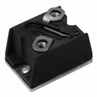
T90RIA120
Description
SCR PHASE CONT 1200V 90A D-55
Manufacturer
Vishay
Datasheet
1.T50RIA20.pdf
(12 pages)
Specifications of T90RIA120
Structure
Single
Number Of Scrs, Diodes
1 SCR
Voltage - Off State
1200V
Current - Gate Trigger (igt) (max)
120mA
Current - On State (it (av)) (max)
90A
Current - On State (it (rms)) (max)
141A
Current - Non Rep. Surge 50, 60hz (itsm)
1780A, 1870A
Current - Hold (ih) (max)
200mA
Mounting Type
Chassis Mount
Package / Case
D-55 T-Module
Mounting Style
Through Hole
Peak Repetitive Off-state Voltage, Vdrm
1.2kV
Gate Trigger Current Max, Igt
120mA
Current It Av
90A
On State Rms Current It(rms)
141A
Peak Non Rep Surge Current Itsm 50hz
1.78kA
Lead Free Status / RoHS Status
Lead free / RoHS Compliant
Other names
*T90RIA120
VS-T90RIA120
VS-T90RIA120
VST90RIA120
VST90RIA120
VS-T90RIA120
VS-T90RIA120
VST90RIA120
VST90RIA120
Available stocks
Company
Part Number
Manufacturer
Quantity
Price


Note
(1)
Document Number: 93756
Revision: 03-Jun-08
BLOCKING
PARAMETER
Maximum peak reverse and
off-state leakage current
RMS isolation voltage
Critical rate of rise of
off-state voltage
TRIGGERING
PARAMETER
Maximum peak gate power
Maximum average
gate power
Maximum peak gate current
Maximum peak
negative gate voltage
Maximum required
DC gate voltage to trigger
Maximum required
DC gate current to trigger
Maximum gate voltage
that will not trigger
Maximum gate current
that will not trigger
Maximum rate of rise of
turned-on current
Available with dV/dt = 1000 V/µs, to complete code add S90 i.e. T90RIA80S90
Medium Power Phase Control Thyristors
SYMBOL
SYMBOL
P
V
dV/dt
I
I
-V
P
dI/dt
RRM
V
V
DRM
G(AV)
I
I
I
ISOL
GM
GD
GT
(Power Modules), 50 A/70 A/90 A
GM
GT
GD
GT
,
For technical questions, contact: ind-modules@vishay.com
T
50 Hz, circuit to base, all terminals shorted, T
T
T
T
T
T
T
T
T
T
T
T
V
I
t
For repetitive value use 40 % non-repetitive
Per JEDEC STD. RS397, 5.2.2.6
g
r
J
J
J
J
J
J
J
J
J
J
J
J
D
< 0.5 µs, t
= 400 mA for T50RIA and I
= T
= T
= T
= T
= T
= - 40 °C
= 25 °C
= T
= - 40 °C
= 25 °C
= T
= T
= 0.67 rated V
J
J
J
J
J
J
J
J
maximum
maximum, linear to 80 % rated V
maximum, t
maximum, f = 50 Hz
maximum, t
maximum
maximum
maximum, rated V
p
≥ 6 µs
DRM
TEST CONDITIONS
p
p
≤ 5 ms
≤ 5 ms
, I
TEST CONDITIONS
TM
DRM
= 2 x rated dI/dt
g
= 500 mA for T70RIA/T90RIA;
applied
Anode supply = 6 V,
resistive load; Ra = 1 Ω
DRM
(1)
J
= 25 °C, t = 1 s
Vishay High Power Products
T50RIA T70RIA T90RIA UNITS
250
100
200
180
160
150
2.5
2.5
4.0
2.5
1.5
0.2
5.0
10
10
50
T..RIA Series
VALUES
270
120
200
180
160
150
4.0
2.5
1.5
0.2
6.0
12
10
60
3
3
3500
500
15
www.vishay.com
270
120
200
180
160
150
4.0
2.5
1.5
0.2
6.0
12
10
60
3
3
UNITS
V/µs
mA
V
A/µs
mA
mA
W
A
V
V
V
3
Related parts for T90RIA120
Image
Part Number
Description
Manufacturer
Datasheet
Request
R

Part Number:
Description:
Manufacturer:
Vishay Semiconductors
Datasheet:

Part Number:
Description:
357-036-542-201 CARDEDGE 36POS DL .156 BLK LOPRO
Manufacturer:
Vishay
Datasheet:
Part Number:
Description:
357-036-542-201 CARDEDGE 36POS DL .156 BLK LOPRO
Manufacturer:
Vishay
Datasheet:
Part Number:
Description:
357-036-542-201 CARDEDGE 36POS DL .156 BLK LOPRO
Manufacturer:
Vishay
Datasheet:
Part Number:
Description:
357-036-542-201 CARDEDGE 36POS DL .156 BLK LOPRO
Manufacturer:
Vishay
Datasheet:
Part Number:
Description:
357-036-542-201 CARDEDGE 36POS DL .156 BLK LOPRO
Manufacturer:
Vishay
Datasheet:
Part Number:
Description:
357-036-542-201 CARDEDGE 36POS DL .156 BLK LOPRO
Manufacturer:
Vishay
Datasheet:
Part Number:
Description:
357-036-542-201 CARDEDGE 36POS DL .156 BLK LOPRO
Manufacturer:
Vishay
Datasheet:
Part Number:
Description:
357-036-542-201 CARDEDGE 36POS DL .156 BLK LOPRO
Manufacturer:
Vishay
Datasheet:
Part Number:
Description:
357-036-542-201 CARDEDGE 36POS DL .156 BLK LOPRO
Manufacturer:
Vishay
Datasheet:
Part Number:
Description:
357-036-542-201 CARDEDGE 36POS DL .156 BLK LOPRO
Manufacturer:
Vishay
Datasheet:
Part Number:
Description:
357-036-542-201 CARDEDGE 36POS DL .156 BLK LOPRO
Manufacturer:
Vishay
Datasheet:
Part Number:
Description:
357-036-542-201 CARDEDGE 36POS DL .156 BLK LOPRO
Manufacturer:
Vishay
Datasheet:
Part Number:
Description:
357-036-542-201 CARDEDGE 36POS DL .156 BLK LOPRO
Manufacturer:
Vishay
Datasheet:
Part Number:
Description:
357-036-542-201 CARDEDGE 36POS DL .156 BLK LOPRO
Manufacturer:
Vishay
Datasheet: