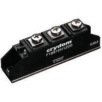
F1892HD1200 Crydom Co., F1892HD1200 Datasheet
F1892HD1200
Manufacturer Part Number
F1892HD1200
Description
MODULE SCR/DIODE 90A 480VAC
Manufacturer
Crydom Co.
Specifications of F1892HD1200
Structure
Series Connection - SCR/Diode
Number Of Scrs, Diodes
1 SCR, 1 Diode
Voltage - Off State
1200V
Current - Gate Trigger (igt) (max)
150mA
Current - On State (it (rms)) (max)
90A (DC)
Current - Non Rep. Surge 50, 60hz (itsm)
1950A @ 60Hz
Mounting Type
Chassis Mount
Package / Case
Module
Peak Repetitive Off-state Voltage, Vdrm
1.2kV
Gate Trigger Current Max, Igt
150mA
Peak Non Rep Surge Current Itsm 50hz
1.95kA
Gate Trigger Voltage Max Vgt
3V
Lead Free Status / RoHS Status
Lead free / RoHS Compliant
Current - Hold (ih) (max)
-
Current - On State (it (av)) (max)
-
Lead Free Status / RoHS Status
Lead free / RoHS Compliant, Lead free / RoHS Compliant
Available stocks
Company
Part Number
Manufacturer
Quantity
Price
Company:

Part Number:
F1892HD1200
Manufacturer:
CRYDOM
Quantity:
27
Company:
Part Number:
F1892HD1200
Manufacturer:
ST
Quantity:
673


1) All parameters at 25°C unless otherwise specified.
2) Available only in SD and SDK circuit configuration.
F18 Series
AVAILABLE OPTIONS
ELECTRICAL SPECIFICATIONS
GENERAL SPECIFICATIONS
GENERAL NOTES
Description
Maximum DC Output Current (Tc = 85°C)
Maximum Voltage Drop @ Amps Peak
Operating Junction Temperature Range
Critical Rate of Rise of On-State Current @ TJ=125°C [A/µs]
Critical Rate of Rise of Off-State Voltage [V/µs]
Repetitive Peak Reverse Voltage (AC Line Nominal) [Vpk]
Maximum Non-Repetitive Surge Current (1/2 Cycle, 60 Hz) [A]
Maximum I²T for Fusing (t=8.3ms) [A²sec]
Maximum Required Gate Current to Trigger @ 25°C [mA]
Maximum Required Gate Voltage to Trigger @ 25°C [V]
Average Gate Power [W]
Maximum Peak Reverse Gate Voltage [V]
Maximum Thermal Resistance, Junction to Ceramic Base per
Chip [°C/W]
Isolation Voltage [Vrms]
Description
Weight (typical)
Torque Required
•
•
• Nine Circuits to Chose from
• UL Recognized E72445
Industry Standard Package and Circuits
Power Control Building Blocks
Symbol
P
dv/dt
V
V
di/dt
I
V
V
R
I
V
TSM
I
G(AV)
T
I
RRM
2
ISOL
GT
GM
D
GT
T
JC
F
J
Terminal Stud Screw : 30 in. lbs. Mounting Screws : 20 in. lbs.
1.55V @ 75 A
-40 - 125°C
1000
2500
25 A
400
100
670
150
27
3.0
0.5
5.0
0.4
1.4V @ 120 A
4.75 oz (135g)
-40 - 125°C
1000
1000
4150
2500
40 A
0.28
100
150
42
3.0
0.5
5.0
1200 (480 VAC)
1400 (530 VAC)
1600 (600 VAC)
400 (120 VAC)
600 (240 VAC)
800 (280 VAC)
1.4V @ 165 A
-40 - 125°C
1000
1500
9350
2500
55 A
0.25
100
150
57
3.0
0.5
5.0
1.4V @ 270 A
-40 - 125°C
15800
1000
1950
2500
90 A
0.14
100
150
92
3.0
0.5
5.0
1.65V @ 300 A
-40 - 125°C
107 (2)
25000
105 A
0.135
1000
2250
2500
100
150
3.0
0.5
5.0
Related parts for F1892HD1200
Image
Part Number
Description
Manufacturer
Datasheet
Request
R

Part Number:
Description:
64-BIT RANDOM ACCESS MEMORY WITH 3-STATE OUTPUTS
Manufacturer:
National Semiconductor

Part Number:
Description:
RELAY SSR 10-35MA INPUT 16 DIP
Manufacturer:
Crydom Co.
Datasheet:
Part Number:
Description:
RELAY SSR 3.5-10VDC INPUT 16 DIP
Manufacturer:
Crydom Co.
Datasheet:

Part Number:
Description:
RELAY SSR 5A 480VAC SIP
Manufacturer:
Crydom Co.
Datasheet:

Part Number:
Description:
RELAY SSR 12A 240VAC DC
Manufacturer:
Crydom Co.
Datasheet:

Part Number:
Description:
RELAY SSR 25A 240VAC DC
Manufacturer:
Crydom Co.
Datasheet:

Part Number:
Description:
POWER CONTROL SSR 15A DC IN
Manufacturer:
Crydom Co.
Datasheet:
Part Number:
Description:
RELAY SSR 125A 480VAC DC INPUT
Manufacturer:
Crydom Co.
Datasheet:
Part Number:
Description:
RELAY SSR 5A 380VAC AC OUT SIP
Manufacturer:
Crydom Co.
Datasheet:
Part Number:
Description:
RELAY SSR 10A 240VAC DC
Manufacturer:
Crydom Co.
Datasheet:
Part Number:
Description:
RELAY SSR 10-35MA INPUT 16 DIP
Manufacturer:
Crydom Co.
Datasheet:
Part Number:
Description:
RELAY SSR 3.5-10VDC INPUT 16 DIP
Manufacturer:
Crydom Co.
Datasheet:
Part Number:
Description:
RELAY SSR AC 2A 120VAC PNL MNT
Manufacturer:
Crydom Co.
Datasheet:

Part Number:
Description:
RELAY SSR AC OUT 1CH 0.3A PCB
Manufacturer:
Crydom Co.
Datasheet:

Part Number:
Description:
RELAY SSR 3A PC MNT W/SNUBER
Manufacturer:
Crydom Co.
Datasheet:
F1892HD1200 Summary of contents
Page 1
F18 Series Industry Standard Package and Circuits • Power Control Building Blocks • • Nine Circuits to Chose from • UL Recognized E72445 AVAILABLE OPTIONS ELECTRICAL SPECIFICATIONS Description Maximum DC Output Current (Tc = 85°C) Maximum Voltage Drop @ Amps ...
Page 2
MECHANICAL SPECIFICATIONS CIRCUIT DIAGRAMS AGENCY APPROVALS E72445 Rev 031710 ...
Page 3
...
Page 4
ANNEX - ENVIROMENTAL INFORMATION ...