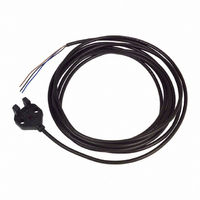
EE-SX871 Omron, EE-SX871 Datasheet - Page 8

EE-SX871
Manufacturer Part Number
EE-SX871
Description
OPTO SENSOR 5MM SLOT L-SHAPE
Manufacturer
Omron
Specifications of EE-SX871
Sensing Distance
0.197" (5mm)
Sensing Method
Transmissive
Output Configuration
NPN - Open Collector/Light-ON
Mounting Type
Chassis Mount, M3 Screw
Current - Supply
35mA
Voltage - Supply
5 V ~ 24 V
Package / Case
Module, Pre-Wired
Termination Style
PCB
Input Current Max
35mA
Optocoupler Output Type
Transistor
Output Voltage
800mV
Input Current
35mA
No. Of Pins
4
Opto Case Style
Module
No. Of Channels
1
Operating Temperature Range
-25°C To +55°C
Operating Voltage Max
24VDC
Operating Voltage Min
5VDC
Rohs Compliant
Yes
Lead Free Status / RoHS Status
Contains lead / RoHS compliant by exemption
Response Time
-
Lead Free Status / Rohs Status
Lead free / RoHS Compliant
Other names
EESX871
OR608
OR608
Available stocks
Company
Part Number
Manufacturer
Quantity
Price
Company:
Part Number:
EE-SX871
Manufacturer:
Omron Electronics
Quantity:
135
J WIRING
For Surge Prevention
If the power supply has surge voltage, connect a Zener diode
withstanding 30 to 35 V or a 0.1 to 1-µF capacitor in parallel to
the power supply to absorb the surge voltage.
If the load is a relay or other small inductive load, connect it to the
EE-SX77/87 as shown below. You must connect a diode for
counter-voltage absorption.
Do not route power lines or high-tension lines in the same
conduit with the EE-SX77/87 to avoid damage or malfunction due
to induction.
EE- -SX770/771/772/870/871/872(A/P/R)
Cat. No. GC APMS-1
1-800-55-OMRON
OMRON ELECTRONICS LLC
One East Commerce Drive
Schaumburg, IL 60173
NOTE: DIMENSIONS SHOWN ARE IN MILLIMETERS. To convert millimeters to inches divide by 25.4.
Output
Output
R
Brown
Blue
09/02
Black
Black
Blue
Brown
Z
D
Relay
: Zener diode
OMRON ON- -LINE
Global -- http://www.omron.com
USA -- http://www.omron.com/oei
Canada -- http://www.omron.com/oci
0.1 to 1 µF
Specifications subject to change without notice.
+V
0 V
Voltage Output
A photomicrosensor with open collector output can be connected
to a device with voltage-input specifications by connecting a
resistor between the power supply and output terminals, as
shown in the following circuit diagram. The value of the resistor is
normally 4.7 kΩ and must withstand a power of 0.5 W at 24 V
and 0.25 W at 12 V.
•
High level:
Low level:
Note: When using a voltage output, always insert a
Note: Refer to the ratings of the photomicrosensor for the rela-
Input voltage (V
Load current (I
Input voltage (V
Sensor
main
circuit
EE-SX77/87 series NPN models with a 4.7-kΩ resistor.
Operation
indicator
(red)
resistor in R
tionship between the residual voltage and load current.
Main
circuit
EE- -SX770/771/772/870/871/872(A/P/R)
C
L
H
) =
) ≦ 0.4 V
) =
L
Output
.
V
CC
R
R+Z
Resistor
Z
=
OUT
L
V
I
OMRON CANADA, INC.
24 V
Toronto, Ontario M1B 5V8
416-286-6465
C
885 Milner Avenue
CC
R
Counter (voltage-input model)
5 to 24 VDC
Load
=
Input terminal (CP)
+24 V (power supply)
= 5.1 mA ≦ 100 mA
4.7 k + 4.7 k
Input impedance:
approx. 4.7 kΩ
4.7 k
(See Note.)
0 V
R
L
Printed in U.S.A.
x 24 V = 12 V
8


