SX150DN Honeywell Sensing and Control, SX150DN Datasheet
SX150DN
Specifications of SX150DN
Available stocks


Related parts for SX150DN


SX150DN Summary of contents
Page 1
... Convenient pressure ranges are available to measure differential, gage and absolute pressures from psi 150 psi. The absolute (A) devices have an in- ternal vacuum reference and an output voltage proportional to absolute pressure ...
Page 2
... P1 for Button, N and A2 s amb housings, pressure applied to P2 for G2 and D4 housings) Maximum ratings Suppy voltage Temperature ranges Operating Storage PERFORMANCE CHARACTERISTICS (V = 5.0 ± 0. °C, common-mode pressure = 0 psig, pressure applied to P1 for Button, N and A2 s amb housings, pressure applied to P2 for G2 and D4 housings ° ...
Page 3
... If the proof pressure is exceeded, even momentarily, the package may leak or burst, or the pressure sensing die may fracture. Note: The proof pressure for the forward gage of all devices in the D4-package is the specified value or 100 psi, whatever is less. 9. The zero pressure offset Min Typ and 35 mV Max for part nos. SX...G2 and SX...D4. ...
Page 4
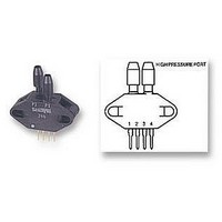
... The SX series devices give a voltage output which is directly proportional to applied pressure. The devices will give an increase in positive going output when increasing pressure is applied to pressure port P1 of the device. If the devices are operated in the backward gage mode, the output will increase with decreases in pressure. The devices are ratiometric to the supply voltage ...
Page 5
... Figure I. Button sensor bridge schematic The resulting differential output voltage easily shown ∆. Since the change in resistance is directly pro- portional to pressure can be written as ± (1) Where the output voltage the sensitivity in mV/V per psi P is the pressure in psi the bridge voltage in volts. ...
Page 6
... Amplifier adjustment procedure 1. Without pressure applied, (a) Short points A and B together as shown in Figure V. Adjust the 1 k common-mode rejection ( pot until the voltage at test point ( equal to the voltage at test point ( ...
Page 7
... again equal (c) Adjust the 2k reference ( adjust pot to get an output voltage ( equal to 1.00V. 2. Apply the fuII-scale pressure and adjust the span adjust pot get the output voltage that is desired to represent full- scale. Table III. For 0 to 70°C operation ...
Page 8
... SX Series Pressure sensors PHYSICAL DIMENSIONS Button package mass package mass 8/10 dimensions in inches (mm) dimensions in inches (mm) July 2008 / 052 www.sensortechnics.com ...
Page 9
... July 2008 / 052 0.470 (11.94) 0.050 typ. (1.27) 0.090 typ. 0.300 (2.29) (7.62) 0.070 (1.78) 0.020 typ. 0.01 (0.51) (0.25) SX Series Pressure sensors dimensions in inches (mm) 0.380 (9.65) 0.285 (7.24) 0.110 typ. (2.79) 0.100 typ. (2.54) dimensions in inches (mm) 9/10 www.sensortechnics.com ...
Page 10
... SX Series Pressure sensors ORDERING INFORMATION SenSym and Sensortechnics reserve the right to make changes to any products herein. SenSym and Sensortechnics do not assume any liability arising out of the application or use of any product or circuit described herein, neither does it convey any license under its patent rights nor the rights of others ...