SCP1000-D11 VTI Technologies, SCP1000-D11 Datasheet
SCP1000-D11
Specifications of SCP1000-D11
Available stocks


Related parts for SCP1000-D11


SCP1000-D11 Summary of contents
Page 1
... Product Family Specification Doc.Nr. 8260800.08 SCP1000 Series Absolute pressure sensor SCP1000-D01 SCP1000-D11 ...
Page 2
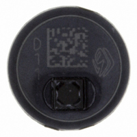
... This version can be recognized from the D01 or D11 marking on the top of the component (see image). If you are using old SCP1000 version (marked using P01 or P03), please use Product Family Specification rev. 0.06. Differences between the old and new SCP1000 version are described in Technical Note 59 (SCP1000 ASIC Update) ...
Page 3
... Power down-pin (PD) during start-up (Phase 1) ...................................................................8 2.1.2 SCP1000 initialization during start-up (Phase 2)...................................................................8 2.1.2.1 SCP1000 initialization status check (optional) ................................................................8 2.1.2.2 SCP1000 checksum error check (optional) ....................................................................9 2.2 Measurement Modes .................................................................................................................9 2.2.1 Measurement modes timing and real time constraints..........................................................9 2.2.1.1 Continuous measurement modes ...................................................................................9 2 ...
Page 4
... Pin Description.........................................................................................................................33 7.2 Recommended Circuit Diagrams ...........................................................................................34 7.3 Recommended PWB Layout ...................................................................................................34 7.4 Assembly instructions ............................................................................................................36 7.5 Tape and reel specifications...................................................................................................36 7.6 Example flex print design .......................................................................................................36 8 Document Revision History .............................................................................................37 9 Contact Information ..........................................................................................................37 VTI Technologies Oy www.vti.fi Subject to changes Doc.Nr. 8260800.08 SCP1000 Series 4/37 Rev.0.08 ...
Page 5
... Interface IC The communication between the SCP1000 and its host micro-controller (µC) is based on a serial interface, an interrupt line and specialized pins used to trigger special functions. The serial interface allows registers' read and write operations and the interrupt line signals events, which require host intervention ...
Page 6
... Temperature output Temperature information is available in every measurement mode for each pressure measurement. VTI Technologies Oy www.vti.fi SCP1000-D01 SCP1000-D11 2.4 V – 3.3 V 2.4 V – 3 kPa – 120kPa 30 kPa – 120kPa 1.5 Pa 1.5 Pa SPI max 500 kHz ...
Page 7
... Phase 2, SCP1000 initialization, start-up status check is optional, see section 2.1.2 cerns SCP1000-D01 products. CSB is tied to AVD SCP1000-D11 (TWI-bus) products (refer to Table n section 7.2). y immediately after powering the system is ded in order to let the power supply and the voltage r the filter capacitors to stabilize needed this y time can be increased ...
Page 8
... Power down-pin (PD) during start-up (Phase 1) SCP1000 has an external power down (PD) pin. In case the system has power management capabilities recommended that during power up the PD pin is tied to DVDD – this way the sensor is forced to remain in power down mode during the stabilization of the power supplies. After ...
Page 9
... Correct EEPROM checksum calculation result is indicated by content of 0x01 in DATARD8. 2.2 Measurement Modes SCP1000 pressure sensor measurement modes are presented in Table 2 below. In three of the measurement modes SCP1000 samples pressure and temperature continuously. In low power mode SCP1000 measures pressure and temperature once after the measurement is triggered. ...
Page 10
... Triggered (low power) measurement mode In triggered measurement mode (low power) SCP1000 stays in standby mode until measurement is externally triggered, see section for more 2.2.4.4 details. The availability of updated pressure and temperature data is signaled as in continuous measurement modes (through the assertion of the DRDY pin and a DRDY bit is set to ‘ ...
Page 11
... In order to switch between the measurement modes necessary first to stop the active mode before activating the new one by writing 0x00 in to OPERATION register. This will instruct SCP1000 to cancel the current operation (SCP1000 enters in to standby mode). After writing 0x00 to OPERATION register and before new measurement mode is activated there should delay. Instead of the 50 ms delay, OPSTATUS register can be read. If OPSTATUS bit in OPSTATUS register is ‘ ...
Page 12
... For more details of pressure data bit level description, see section 3.2 (Table 12). Pressure data is presented in integer format. When operating within the nominal operation range (30…120 kPa) the output of the SCP1000 changes between 120000 and 480000. The output is converted from decimal format to [Pa] as follows: ...
Page 13
... Once the mode has been started the only interface activity required is periodic reading of the output pressure and temperature registers (in applications where the temperature is not needed the output temperature reading can be omitted), see section 2.2.1.1. SCP1000 operation parameters in high resolution measurement mode are presented in Table 5 below. Table 5. SCP1000 operation parameters in high resolution mode. ...
Page 14
... In high speed measurement mode pressure and temperature are measured continuously the conversion time is shortened at the cost of output resolution. This allows an increased output refresh rate of approximately 9 Hz. SCP1000 operation parameters in high speed measurement mode are presented in Table 6 below. Table 6. SCP1000 operation parameters in high speed mode. Symbol ...
Page 15
... CFG register (see section 3.3). The CFG register contents are presented in Table 8 below. Table 8. Recommended CFG register contents. Resolution 17 bits (default) 15 bits SCP1000 operation parameters in low power measurement mode are presented in Table 9 below. Table 9. SCP1000 operation parameters in low power mode. Symbol Parameter V Supply voltage (AVDD & DVDD) ...
Page 16
... In order to decrease further the current consumption in cases where there are long time intervals between the measurements, SCP1000 has a built in power down mode, which can be activated through the PD pin. SCP1000 will stay in power down mode as long as the PD signal is high. In power down mode every digital output pin of SCP1000 tristates. ...
Page 17
... Addressing Space SCP1000 register contents and bit definitions are described in more detail in next sections. All registers are read and written through the serial host interface. 3.1 Register Description SCP1000 register types: - direct access registers, - indirect access registers and - EEPROM registers. Table 10. List of SCP1000 direct and indirect access registers and EEPROM registers. ...
Page 18
... Others Reserved VTI Technologies Oy www.vti.fi Initial Name Description Value 00h DATA Indirect access data Initial Name Description Value 00h ADDR Indirect register address Initial Name Description Value 00h OPERATION See operation description in Table 11. Subject to changes Doc.Nr. 8260800.08 SCP1000 Series 18/37 Rev.0.08 ...
Page 19
... DATARD16 read operation) Reserved 0 STARTUP Start-up status 0 – start-up procedure is finished 1 – start-up procedure is running Initial Name Description Value Reserved 000 PRES_MSB Pressure data MSB (3 bits) 00h DATA 8 bit data from EEPROM register Subject to changes Doc.Nr. 8260800.08 SCP1000 Series 19/37 Rev.0.08 ...
Page 20
... Indirect Access Registers SCP1000 indirect access register contents and bit definitions are described in this section. Indirect access registers can be accessed through the serial interface using the OPERATION, DATAWR, ADDPTR and DATARD16 registers (see section 3.3.1). ...
Page 21
... EEPROM memory SCP1000 has internal non-volatile memory for calibration and configuration data. Memory content will be programmed during production. Initial configuration is loaded during sensor start-up. EEPROM register contents and bit definitions are described in this section. User has access to 4 EEPROM registers ...
Page 22
... Write 0x05 in direct register OPERATION (0x03) o Wait 15 ms (minimum wait value) o Read direct register DATARD8 (0x1F for SPI, 0x7F for TWI), the register content is in bits o [7:0], see section 3.2 for further information. VTI Technologies Oy www.vti.fi Subject to changes Doc.Nr. 8260800.08 SCP1000 Series 22/37 Rev.0.08 ...
Page 23
... SCP1000 is done using MOSI, MISO, SCK and CSB. CSB selects the chip on multi-chip SPI bus, SCK is the serial data clock, MOSI is the data line from master to slave (Master Out Slave In) and MISO is data line from slave to master (Master In Slave Out). SCP1000 is configured to SPI slave mode (see Figure 8). ...
Page 24
... Examples of SPI communication Examples SPI communication (8 and 16 bit read / write operations) are presented in Figure 10 below. Figure 10. SPI communication examples. VTI Technologies Oy www.vti.fi Subject to changes Doc.Nr. 8260800.08 SCP1000 Series 24/37 Rev.0.08 ...
Page 25
... SDA, bi-directional data line. o The SCL pin of SCP1000 is an input pin (SCP1000 never controls the SCL line). Data is transferred in and out of the sensor through the bi-directional SDA pin. SDA has an open-drain output external pull-up resistor to DVDD is required (see Figure 11). The minimum value for SDA pull-up resistor is 2 kΩ ...
Page 26
... REGISTER ADDRESS (µC → SCP1000) Master sends register address to SCP1000 MSB first. REGISTER DATA (SCP1000 → µC) The SCP1000 registers can bits wide bit write is performed by sending MSB first bits write is performed by sending two bytes (MSB first). After each byte, the slave sends an acknowledgement bit. ...
Page 27
... LSB content to SDA line) 31. MASTER NOT ACKNOWLEDGE (master terminates the data transfer by sending not acknowledge bit) 32. STOP BIT (master sets the bus free) VTI Technologies Oy www.vti.fi 14. 13. 15. 12. Subject to changes Doc.Nr. 8260800.08 SCP1000 Series 19. 18. 16. 17. 27/37 Rev.0.08 ...
Page 28
... Figure 15. TWI frame format for 16 bit read operation (numbers from refer to list above). VTI Technologies Oy www.vti.fi 25. 24. 27. 28. 26. Subject to changes Doc.Nr. 8260800.08 SCP1000 Series 32. 31. 29. 30. 28/37 Rev.0.08 ...
Page 29
... Electrical Characteristics 5.1 Absolute Maximum Ratings The absolute maximum ratings of SCP1000 are presented in Table 14 below. Table 14. Absolute maximum ratings of SCP1000. Parameter Supply voltage ( Voltage at input / output pins ESD (Human body model) Storage temperature Proof pressure Ultrasonic cleaning 1 Referred to DVDD 5.2 Power Supply The analog and digital supply voltage levels (AVDD and DVDD) should always be equal ...
Page 30
... LS1 T LS2 Fsck T SET T HOL Load T VAL1 capacitance at MISO < Load T LZ capacitance at MISO < Load T VAL2 capacitance at MISO < Subject to changes Doc.Nr. 8260800.08 SCP1000 Series T T LS2 LH LSB LSB out Min Typ Max Unit 100 ns 100 ns 100 ns 100 ns 1 MHz 100 ns 100 ns 50 ...
Page 31
... Conditions Symbol T hdsta F scl T high T low T susta T hddat T sudat T susto T buf Subject to changes Doc.Nr. 8260800.08 SCP1000 Series Stop tbuf thddat tsusto Min Typ Max Unit 600 ns 400 kHz 1300 ns 600 ns 600 ns 300 ns 100 ns 600 ns 1300 ns 31/37 ...
Page 32
... Package Characteristics 6.1 Dimensions SCP1000 package dimensions are presented in Figure 19 below (dimensions in [mm]). Figure 19. SCP1000 package dimensions. VTI Technologies Oy www.vti.fi Subject to changes Doc.Nr. 8260800.08 SCP1000 Series 32/37 Rev.0.08 ...
Page 33
... SPI data output Not connected SPI chip select Connect to analog supply voltage Analog supply voltage Analog supply voltage Analog ground Analog ground Analog ground Analog ground Connect to analog ground Connect to analog ground Subject to changes Doc.Nr. 8260800.08 SCP1000 Series SCP1000-D11 (TWI) 33/37 Rev.0.08 ...
Page 34
... In order to achieve high performance and low noise level it is recommended both AVDD and DVDD have their own supply voltage regulators and analog ground plane is separated from digital ground plane near SCP1000. If high performance is not needed, DVDD and AVDD can be supplied from one regulator. Recommended circuit diagrams for SCP1000 are presented in Table 19 below. ...
Page 35
... Recommended PWB pad layout for SCP1000 is presented in Figure 21 below (dimensions in [mm], tolerances ±0.05 mm). Figure 21. Recommended PWB pad layout for SCP1000. Recommended PWB layout for SCP1000 with SPI and TWI interfaces is presented in Table 21 below (circuit diagram presented in Table 19 above). Table 21. SCP1000 recommended PWB layouts (not in real size, for reference only). ...
Page 36
... Example flex print design The electric connections between the SCP1000 sensor and electronics of an application can be carried out by using a flex print. An example flex print design for SCP1000 is presented in Figure 22 and Figure 23 below. These flex print designs are designed by following the recommended circuit diagrams and PWB layouts presented in sections 7 ...
Page 37
... Section "6.2 Solder instructions" renamed to "7.4 Assembly instructions", - Section "7.5 Tape and reel specifications" added - Minor language corrections Contact information 0.05 30.08.2006 Minor updates in SCP1000 operation parameters, examples for temperature conversion to [°C] added (section 2.2.3.1). 0.06 14.11.2006 Minor updates in SCP1000 data refresh rates. 0.07 14 ...