A16-1NRN Omron, A16-1NRN Datasheet - Page 14
A16-1NRN
Manufacturer Part Number
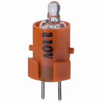
A16-1NRN
Description
NEON LAMP 110V RED FOR A16
Manufacturer
Omron
Type
Neon Lamp, 110 VoltsACr
Series
A16r
Datasheets
1.M2DA-7001.pdf
(265 pages)
2.A16-1NRN.pdf
(30 pages)
3.A16-2.pdf
(27 pages)
4.A165-CAA.pdf
(17 pages)
Specifications of A16-1NRN
Accessory Type
Neon Lamp Replacement
Supply Voltage
110V
Base Type
Bi-Pin
Colour
Red
Current Rating
1.5mA
Svhc
No SVHC (15-Dec-2010)
Illumination Colour
Red
Operating Lifetime
10000h
Voltage Rating Vac
110V
Average Bulb Life
1000
Color
Red
Illumination
Illuminated
Height
13 mm
Illumination Color
Red
Mounting Style
Snap In
Termination Style
Tabs
Lamp Base Type
Bi-Pin
Rohs Compliant
Yes
Lead Free Status / RoHS Status
Lead free / RoHS Compliant
For Use With/related Products
A16 Series
For Use With
Z1397 - SWTCH KNOB RND 3POS DPDT ILL REDZ1394 - SWTCH KNOB RND 2POS SPDT ILL REDZ1391 - SWTCH KNOB RND 2POS SPDT ILL REDZ1385 - SWITCH KNB RECT 3POS DPDT ILLZ1382 - SWITCH KNB RECT 2POS SPDT ILLZ1379 - SWITCH KNB RECT 2POS SPDT ILLZ1373 - SWITCH KNOB SQ 3-POS DPDT ILLZ1370 - SWITCH KNOB SQ 2-POS SPDT ILLZ1367 - SWITCH KNOB SQ 2-POS SPDT ILLZ1309 - SWITCH PB RND MOM DPDT ILLUM REDZ1305 - SWITCH PB RECT MOM DPDT ILLUMZ1301 - SWITCH PB SQ MOM DPDT ILLUM RED
Lead Free Status / Rohs Status
Lead free / RoHS Compliant
Other names
A161NRN
Z1342
Z1342


A16
Note: Lock stroke is only for alternate operation.
Operation
Wiring for Screw-Less Clamps
Mounting Wires
Features
Operating force (OF) max.
Releasing force (RF) min.
Total travel (TT)
Pretravel (PT) max.
Lock stroke (LTA) min.
(See note.)
Operating Characteristics
Terminal Arrangement
1. Strip a length of 10 mm off the end of the wire (allowable
2. Bunch wire strands together and straighten them.
3. Insert the wire into the insertion hole while pressing the
Mounting Precautions
1. The mounting panel thickness must be 0.5 to 3.2 mm.
2. The mounting ring must be tightened to a torque 0.29 to 0.49 N m.
3. The mounting hole must be cut out in the way described previously. The dimension A is the length required for removing the Switch when
4. Be sure to mount the Case to the Switch with the correct orientation. Mount with the mark on the Case facing in the same direction as the
5. When using stranded wires with the Screw-Less Clamp, wrap the ends of the wires together first.
6. When wiring, insert the wires until they come into contact with something. After wiring, pull on the wires to check that they are secure.
7. After wiring, ensure that continuous pressure is not applied to the terminals.
8. Be sure to perform wiring correctly. Refer to internal connections diagrams and check the terminal numbers before wiring.
The voltage-reduction circuit is built in.
range: 10 1 mm).
release button at the side of the hole. (Using a precision
screwdriver is recommended.)
it is in the mounted state. If Switches are mounted side-by-side separated by less than the specified distance, it may not be possible to
remove the Switch.
side of the Switch with the direction arrow or the word TOP.
Case
Side with direction arrow
DPDT lighted models
(Bottom view)
mark
Type
Switch
2.45 N
0.29 N
Approx. 3 mm
2.5 mm
0.5 mm
Direction arrow
SPDT
IP40
4.41 N
Screw-Less Clamps and Voltage Reduction Unit
Removing Wires
Remove wires by pulling them while pressing the release button.
Note: When reusing wires that have already been locked, cut off
White
Black
Black
Red
4. Let go of the release button to lock the wire into place.
5. After locking, pull on the wire gently to confirm that it is
DPDT
Voltage-reduction lighting models with Screw-Less Clamps
(A16L-jT1-2S, A16L-jT2-2S) incorporate voltage-reduction
circuits.
securely locked.
Pushbutton Switch
the end of the wire and strip the wire again before using.
Case
2.94 N
Black
DPDT lighted models
Red
mark
SPDT
White
Red
Black
Black
Oil-resistant IP65
Side indicating TOP
(Bottom view)
Switch
TOP mark
4.91 N
DPDT
A16
65
Related parts for A16-1NRN
Image
Part Number
Description
Manufacturer
Datasheet
Request
R

Part Number:
Description:
SWITCH PB SQUARE MOM SPDT GREEN
Manufacturer:
Omron
Datasheet:

Part Number:
Description:
SWITCH PB SQUARE MOM SPDT WHITE
Manufacturer:
Omron
Datasheet:
Part Number:
Description:
SWITCH PB SQUARE MOM SPDT YELLOW
Manufacturer:
Omron
Datasheet:
Part Number:
Description:
SWITCH PB RECTANG MOM SPDT BLUE
Manufacturer:
Omron
Datasheet:
Part Number:
Description:
SWITCH PB RECTANG MOM SPDT YEL
Manufacturer:
Omron
Datasheet:
Part Number:
Description:
SWITCH PB SQUARE MOM SPDT BLUE
Manufacturer:
Omron
Datasheet:
Part Number:
Description:
SWITCH PB SQUARE MOM SPDT RED
Manufacturer:
Omron
Datasheet:
Part Number:
Description:
SWITCH PB RECTANG MOM SPDT GREEN
Manufacturer:
Omron
Datasheet:
Part Number:
Description:
SWITCH PB RECTANG MOM SPDT RED
Manufacturer:
Omron
Datasheet:

Part Number:
Description:
SWITCH PB RECTANG MOM SPDT WHITE
Manufacturer:
Omron
Datasheet:
Part Number:
Description:
SWITCH PB ROUND MOM SPDT BLUE
Manufacturer:
Omron
Datasheet:
Part Number:
Description:
SWITCH PB ROUND MOM SPDT GREEN
Manufacturer:
Omron
Datasheet:
Part Number:
Description:
SWITCH PB ROUND MOM SPDT RED
Manufacturer:
Omron
Datasheet:
Part Number:
Description:
SWITCH PB ROUND MOM SPDT WHITE
Manufacturer:
Omron
Datasheet:
Part Number:
Description:
SWITCH PB ROUND MOM SPDT YELLOW
Manufacturer:
Omron
Datasheet: