AT494 NKK Switches, AT494 Datasheet - Page 4
AT494
Manufacturer Part Number
AT494
Description
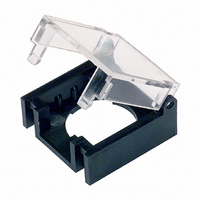
PROTECTIVE GUARD KB SER SQ&RND
Manufacturer
NKK Switches
Type
Protective Guardr
Series
ATr
Specifications of AT494
Accessory Type
Protective Guard
Height
11.5 mm
Length
19 mm
Mounting Style
SMD/SMT
Termination Style
Snap On
Width
19 mm
Brand/series
KB Series
Switch Type
Push Button Switch
Operating Temp Range
-25C to 70C
For Use With/related Products
KB Series - Square/Round
For Use With
360-2019 - SWITCH PB ILLUM DPDT ALT GRN SLD360-2018 - SWITCH PB ILLUM DPDT ALT AMB SLD360-2017 - SWITCH PB ILLUM DPDT ALT RED SLD360-2013 - SWITCH PB ILLUM DPDT ALT GRN SLD360-2012 - SWITCH PB ILLUM DPDT ALT AMB SLD360-2011 - SWITCH PB ILLUM DPDT ALT RED SLD360-2010 - SWITCH PB ILLUM DPDT MOM GRN SLD360-2009 - SWITCH PB ILLUM DPDT MOM AMB SLD360-2008 - SWITCH PB ILLUM DPDT MOM RED SLD360-2004 - SWITCH PB ILLUM DPDT MOM GRN SLD360-2003 - SWITCH PB ILLUM DPDT MOM AMB SLD360-2002 - SWITCH PB ILLUM DPDT MOM RED SLD360-2001 - SWITCH PB ILLUM SPDT ALT GRN SLD360-2000 - SWITCH PB ILLUM SPDT ALT AMB SLD360-1999 - SWITCH PB ILLUM SPDT ALT RED SLD360-1995 - SWITCH PB ILLUM SPDT ALT GRN SLD360-1994 - SWITCH PB ILLUM SPDT ALT AMB SLD360-1993 - SWITCH PB ILLUM SPDT ALT RED SLD360-1992 - SWITCH PB ILLUM SPDT MOM GRN SLD360-1991 - SWITCH PB ILLUM SPDT MOM AMB SLD360-1990 - SWITCH PB ILLUM SPDT MOM RED SLD360-1986 - SWITCH PB ILLUM SPDT MOM GRN SLD360-1985 - SWITCH PB ILLUM SPDT MOM AMB SLD360-1984 - SWITCH PB ILLUM SPDT MOM RED SLD
Lead Free Status / RoHS Status
Lead free / RoHS Compliant
Other names
360-1004


NKK Switches • email: sales@nkkswitches.com • Phone (480) 991-0942 • Fax (480) 998-1435
Pole
DP
SP
Keyway
Without
K
K
S
Housing available in black only. Shroud is an integral part of the switch body.
.551" Square
.551" Square
Model
KB15
KB16*
KB25
KB26*
Panel thicknesses, when using optional accessories, are shown with the accessories at the end of this KB section.
* When in latchdown position for the alternate circuit, cap position is 1.4mm (.055") above the built-in bezel.
The bezel is an integral part of the switch body. One mounting nut AT057 supplied with each switch.
(
Normal
(12.3) Dia
.484
Plunger Position
ON
ON
ON
ON
) = Momentary
Bushing Mounting
Panel Thickness:
(.020 ~ .315")
0.5 ~ 8mm
Down
(ON)
(ON)
ON
ON
The bezel is an integral part of the switch body.
SHAPES & MOUNTING TYPES
M
C
POLES & CIRCUITS
.551" Round
.551" Round
2-3 5-6
Normal
Connected Terminals
2-3
Bushing Mounting
Snap-In Mounting
HOUSING
Panel Cutouts
.071
(1.8)
(12.3) Dia
.484
Miniature Pushbuttons
(4.9)
.193
2-1 5-4
Down
2-1
Keyway
With
DPDT
SPDT
Notes: Switch is marked with "+" and "-".
Throw & Power/Lamp Schematics
Panel Thickness:
Lamp circuit is isolated and requires
external power source.
(.039 ~ .138")
1.0 ~ 3.5mm
N
R
3
3
www.nkkswitches.com
.551" x .728" Rectangular
.551" x .728" Rectangular
2
(COM)
Snap-In Mounting
1
2 (COM)
6
1
Series KB
5
.047
(1.2) R
.268
(6.8)
4
L (+)
L (+)
(12.3) Dia
.484
(-) L
(-) L
12-02
Related parts for AT494
Image
Part Number
Description
Manufacturer
Datasheet
Request
R

Part Number:
Description:
Rocker Switches & Paddle Switches High In-rush Rated Rocker Switch
Manufacturer:
NKK Switches
Datasheet:
Part Number:
Description:
Rocker Switches & Paddle Switches High In-rush Rated Rocker Switch
Manufacturer:
NKK Switches
Datasheet:
Part Number:
Description:
Rocker Switches & Paddle Switches High In-rush Rated Rocker Switch
Manufacturer:
NKK Switches
Datasheet:
Part Number:
Description:
Rocker Switches & Paddle Switches High In-rush Rated Rocker Switch
Manufacturer:
NKK Switches
Datasheet:

Part Number:
Description:
Pushbutton Switches SPST ON(OFF) 15/32'
Manufacturer:
NKK Switches
Datasheet:

Part Number:
Description:
Pushbutton Switches SPST OFF(ON) 15/32'
Manufacturer:
NKK Switches
Datasheet:

Part Number:
Description:
Pushbutton Switches ON(OFF) NORM CLSD 3A RED PLNGR LUG 15/32
Manufacturer:
NKK Switches
Datasheet:

Part Number:
Description:
Pushbutton Switches SPDT ON-(ON)
Manufacturer:
NKK Switches
Datasheet:

Part Number:
Description:
Pushbutton Switches ON-(ON) RND BUSH MNT RED LED RED/RED CAP
Manufacturer:
NKK Switches
Datasheet:
Part Number:
Description:
Pushbutton Switches SPST ON-(OFF) STRT
Manufacturer:
NKK Switches
Datasheet:
Part Number:
Description:
Pushbutton Switches OFF(ON) NORM OPEN 3A RED CAP LUG 15/32
Manufacturer:
NKK Switches
Datasheet:
Part Number:
Description:
Pushbutton Switches ILLUM PUSHBUTTON SPDT
Manufacturer:
NKK Switches
Datasheet:
Part Number:
Description:
Pushbutton Switches OFF(ON) NORM OPEN 3A BLK CAP LUG 15/32
Manufacturer:
NKK Switches
Datasheet:
Part Number:
Description:
Pushbutton Switches SPST NO Metric Thrd Blk Plunge w/Blu Cap
Manufacturer:
NKK Switches
Datasheet:
Part Number:
Description:
Pushbutton Switches SPST OFF-(ON) NO 3A
Manufacturer:
NKK Switches
Datasheet: