B32-1280 Omron, B32-1280 Datasheet - Page 9
B32-1280
Manufacturer Part Number
B32-1280
Description
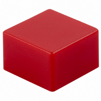
KEYCAP 9MM SQ RED FITS 12MM SER
Manufacturer
Omron
Type
Key Cap for Mechanical Key Switchesr
Specifications of B32-1280
Switch Type
Tactile
Shape
Square
Color
Red
Illumination
Non-Illuminated
Mounting Type
Slip On
Size
9.00mm L x 9.00mm W x 5.50mm H
Height
9 mm
Length
9 mm
Actuator / Cap Color
Red
External Height
9mm
Length/height, External
5.5mm
External Width
9mm
Knob / Dial Style
Square
Features
9 X 9 Mm
For Use With
SW856 - SWITCH TACT 12MM 350GF H=7.3MMSW839 - SWITCH TACT 12MM 200GF H=7.3MMSW838 - SWITCH TACT 12MM SQ 350GFSW969 - SWITCH TACT 12MM 130GF H=7.3MMSW801 - SWITCH TACT 12MM 130GF H=7.3MMSW967 - SWITCH TACT 12MM 260GF H=7.3MMSW835 - SWITCH TACT 12MM 130GF H=7.3MMSW970 - SWITCH TACT 12MM 130GF H=7.3MMSW1140 - MECHANICAL KEYSWITCHSW413 - SWITCH TACT 12MM MOM N/O 130GFSW414 - SWITCH TACT 12MM MOM N/O 260GFSW422 - SWITCH TACT 12MM MOM 200GF SEALD
Lead Free Status / RoHS Status
Lead free / Not applicable
For Use With/related Products
B3F and B3W Series
Lead Free Status / Rohs Status
Lead free / RoHS Compliant
Other names
B321280
SW256
SW256


Precautions
B3FS-1050P
B3S
Note:
Standards
Package
Heat resistance
Standards
Package
Heat resistance
Tape drawing direction
Switches with ground terminals are packaged with the
ground terminal on the opposite side of the guide hole.
1.5
8.7
+0.1
0
dia.
0.06
Reel
Reel (made of paper)
7
(22)
1.5
+0.1
12±
0
13 dia.
4±
dia.
Tape drawing direction
Label
0.1
Conforms to JEITA.
1,000 Switches
60 ° C for 24 hours (without deformation)
Conforms to JEITA.
1,000 Switches
50 ° C for 24 hours (without deformation)
0.1
9.4
1.5
12±
2
4±
Tape drawing direction
0.1
Tape drawing direction
0.1
1.75±
0.4
380±2 dia.
7.5
Label
0.1
2
330 dia.
16±
4.7
13 dia.
0.3
1.75
7.5
(8.1)
16
21.5
LEDs (B3J)
Make sure that the polarity of the LEDs is correct. The polarity is
not indicated on the Switch, but the positive pole is located on the
back surface of the Switch on the side without the OMRON mark.
Connect limiting resistors to the LEDs. The Switch does not have
built-in limiting resistors, so satisfy the LED characteristics by
obtaining the limiting resistance according to the following formula
based on the voltage to be used.
Limiting resistance (R)=
0.5
50
30
10
50
40
30
20
10
5
3
1
0
−20
1.5
1.6
(Voltage used (E) – LED forward voltage (VF))
R
0
1.7
E
Green
Yellow
LED forward current (IF)
20
Red
I
V
F
F
Ambient temperature Ta (°C)
1.8
40
Forward voltage V
1.9
Red
Yellow/Green
60
Precautions
2.0
F
2.1
(V)
80
(Ω)
7
Related parts for B32-1280
Image
Part Number
Description
Manufacturer
Datasheet
Request
R

Part Number:
Description:
KEYCAP 12MM SQ ORANGE FITS 12MM
Manufacturer:
Omron
Datasheet:

Part Number:
Description:
KEYCAP 12MM GRN FITS 12MM
Manufacturer:
Omron
Datasheet:

Part Number:
Description:
KEYCAP 12MM LT GRN FITS 12MM
Manufacturer:
Omron
Datasheet:

Part Number:
Description:
KEYCAP 12MM SQ RED FITS 12MM
Manufacturer:
Omron
Datasheet:

Part Number:
Description:
KEYCAP 12MM SQ WHITE FITS 12MM
Manufacturer:
Omron
Datasheet:

Part Number:
Description:
KEYCAP 12MM SG BLK FITS 12MM SER
Manufacturer:
Omron
Datasheet:

Part Number:
Description:
KEYCAP 12MM SG LT GREY FITS 12MM
Manufacturer:
Omron
Datasheet:

Part Number:
Description:
KEYCAP 12MM SQ BLUE FITS 12MM
Manufacturer:
Omron
Datasheet:

Part Number:
Description:
KEYCAP 12MM SQ YELL FITS 12MM
Manufacturer:
Omron
Datasheet:

Part Number:
Description:
KEYCAP 4MM SQ ORANGE FOR 6MM B3F
Manufacturer:
Omron
Datasheet:

Part Number:
Description:
B3F ROUND KEY CAP LT GRAY
Manufacturer:
Omron
Datasheet:

Part Number:
Description:
Tactile Switch Key Top
Manufacturer:
OMRON [Omron Electronics LLC]
Datasheet:
Part Number:
Description:
Tactile Switch Key Top
Manufacturer:
OMRON [Omron Electronics LLC]
Datasheet: