A165L-TA Omron, A165L-TA Datasheet - Page 21
A165L-TA
Manufacturer Part Number
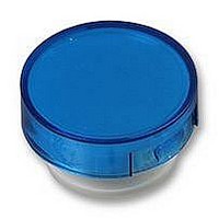
A165L-TA
Description
CAP 16 SERIES ROUND BLUE
Manufacturer
Omron
Series
A16r
Specifications of A165L-TA
Switch Type
Pushbutton
Shape
Round
Color
Blue
Illumination
Illumination Optional
Mounting Type
Snap Fit
Size
15.10mm Dia x 3.50mm H
Svhc
No SVHC (15-Dec-2010)
Colour
Blue
External Diameter
15.1mm
Height
3.5mm
Panel Cutout Diameter
16mm
Mounting Hole Dia
16mm
Lens Colour
Blue
Lens Height
3.5mm
Lens Diameter
15.1mm
Rohs Compliant
Yes
For Use With
A16 Series Pushbutton Switches
Lead Free Status / RoHS Status
Lead free / RoHS Compliant
For Use With/related Products
A16 Series
Lead Free Status / Rohs Status
Lead free / RoHS Compliant
Other names
A165LTA


Dimensions
Panel Cutouts
Solder Terminals and Screw-less Clamp Connectors
Terminal Arrangement
Models without Reduced-voltage Lighting
Solder Terminals
Note:• Make sure the thickness of the mounting panel is between 0.5 and 3.2
Rectangular A16@-@J/M16@-@J
Dimensions of
Terminal Holes
16
• If the panel is to be finished with coating, etc., make sure that the panel
• Figures in parentheses are for Screw-less Clamp Connectors.
+0.2
1.5
2.8
0
mm. If, however, a Switch Guard or Dust Cover is used, the thickness
of the mounting panel must be between 0.5 and 2 mm.
meets the specified dimensions after coating.
dia.
(Top View)
(25 min.)
24 min.
2.6
0.9
Lamp terminal
7.4
Lighted SPDT Switches
(33 min.)
19 min.
12.2
18
Note: The L+ is not shown on the Switch.
Square A16@-A/M16@-A
Round A16@-T/M16@-T
16
+0.2
0
Terminal Arrangement
dia.
(Top View)
(Bottom View)
(25 min.)
19 min.
(Non-lighted Pushbutton Switches are also provided with lamp terminals.)
(33 min.)
COM
SW1
19 min.
NC
NO
L-
PCB Terminals
1.5
2.8
Note:• Ensure that the variation in the distance between the centers of
Dimensions of
Terminal Holes
Rectangular A16@-J/M16@-J
9.1 ± 0.05
14.7 ± 0.05 dia.
Lamp terminal
• Make sure the thickness of the mounting panel is between 0.5 and 3.2
• If the panel is to be finished with coating, etc., make sure that the panel
neighboring mounting holes is less than ±0.1 mm.
mm. If, however, a Switch Guard or Dust Cover is used, the thickness
of the mounting panel must be between 0.5 and 2 mm.
meets the specified dimensions after coating.
2.6
0.9
16
+0.2
0
5.1 ± 0.05
dia.
(Top View)
7.4
24 min.
Lighted DPDT Switches
12.2
18
Note: The L+ is not shown on the Switch.
24 min.
Terminal Arrangement
Square A16@-A/M16@-A
Round A16@-T/M16@-T
(Bottom View)
16
+0.2
0
dia.
(Top View)
(25 min.)
19 min.
COM
SW1
NC
NO
L-
COM
SW2
NC
NO
(Unit: mm)
(33 min.)
19 min.
A16
21
Related parts for A165L-TA
Image
Part Number
Description
Manufacturer
Datasheet
Request
R

Part Number:
Description:
SWITCH PB SQ ALT DPDT GREEN
Manufacturer:
Omron
Datasheet:
Part Number:
Description:
SWITCH PB SQ MOM DPDT GREEN
Manufacturer:
Omron
Datasheet:
Part Number:
Description:
SWITCH PB SQ ALT DPDT RED
Manufacturer:
Omron
Datasheet:
Part Number:
Description:
SWITCH PB SQ MOM DPDT RED
Manufacturer:
Omron
Datasheet:
Part Number:
Description:
SWITCH PB SQ ALT DPDT WHITE
Manufacturer:
Omron
Datasheet:
Part Number:
Description:
SWITCH PB SQ MOM DPDT WHITE
Manufacturer:
Omron
Datasheet:
Part Number:
Description:
SWITCH PB SQ ALT DPDT YELLOW
Manufacturer:
Omron
Datasheet:
Part Number:
Description:
SWITCH PB SQ MOM DPDT YELLOW
Manufacturer:
Omron
Datasheet:
Part Number:
Description:
SWITCH PB RECT ALT DPDT GREEN
Manufacturer:
Omron
Datasheet:
Part Number:
Description:
SWITCH PB RECT MOM DPDT GREEN
Manufacturer:
Omron
Datasheet:
Part Number:
Description:
SWITCH PB RECT MOM DPDT RED
Manufacturer:
Omron
Datasheet:
Part Number:
Description:
SWITCH PB RECT ALT DPDT WHITE
Manufacturer:
Omron
Datasheet:
Part Number:
Description:
SWITCH PB RECT MOM DPDT WHITE
Manufacturer:
Omron
Datasheet: