A6RS-101RF Omron, A6RS-101RF Datasheet - Page 3
A6RS-101RF
Manufacturer Part Number
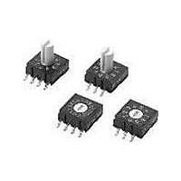
A6RS-101RF
Description
SMT ROTARY DIP
Manufacturer
Omron
Series
A6RSr
Specifications of A6RS-101RF
Switch Type
DIP
Actuator Type
Rotary for Tool
Circuit
BCD
Number Of Positions
10
Contact Rating @ Voltage
0.025A @ 24VDC
Actuator Level
Flush
Mounting Type
Surface Mount
Orientation
Top Actuated
Washable
No
Actuator
Rotary
Terminal Pitch
2.54 mm
Termination Style
Solder Pad
No. Of Switch Positions
10
Actuation Type
Flat
Pitch Spacing
2.54mm
Contact Current Dc Max
25mA
Switch Mounting
Surface
Svhc
No SVHC (15-Dec-2010)
Contact
RoHS Compliant
Actuator Style
Flat
Rohs Compliant
Yes
Lead Free Status / RoHS Status
Lead free / RoHS Compliant
Lead Free Status / RoHS Status
Lead free / RoHS Compliant
Other names
A6RS101RF


A6RS
Precautions
■
Note:
■
Soldering
• Make sure that Surface-mounting Rotary DIP Switches are set to
• Observe the following conditions for reflow soldering the A6RS.
Washing
The A6RS cannot be washed. Attempting to wash it may result in
malfunction due to flux and foreign matter from the PCB flowing
into the A6RS together with the cleaning fluid.
RoHS Compliant
The "RoHS Compliant" designation indicates that the listed mod-
els do not contain the six hazardous substances covered by the
RoHS Directive.
Reference: The following standards are used to determine com-
pliance for the six substances.
• Lead: 1,000 ppm max.
• Mercury: 1,000 ppm max.
• Cadmium: 100 ppm max.
• Hexavalent chromium: 1,000 ppm max.
• PBB: 1,000 ppm max.
• PBDE: 1,000 ppm max.
Environment for Storage and Use
To prevent discoloration of the terminals and other problems dur-
ing storage, do not store the A6RS in locations subject to the fol-
lowing conditions.
Also, the A6RS is not waterproof or splash-resistant. Do not
install or use the A6RS in locations that are subject to contact
with water.
Do not subject the A6RS to freezing or condensation.
0 before soldering. Misalignment may result in reducing the op-
erating load capacity.
(Measurement location: Top of Switch)
1. High temperatures or humidity
2. Corrosive gases
3. Direct sunlight
Precautions for safe use
Precautions for Correct Use
Refer to Safety Precautions in the DIP Switches (Cat. No. X040) for details on general safety precautions.
260 max.
230
180
150
Preheating
60 to 150
Actual
soldering
60 max.
Time (s)
Using Flux
The type of flux or the amount or method in which it is applied,
including its use in reflow soldering, can have adverse effects on
Switch performance. Assess the proper flux, conditions, and
methods prior to using it.
Handling
Do not apply excessive operating force to the Switch. Otherwise
the Switch may be damaged or deformed, and the switch mecha-
nism may malfunction as a result. Do not apply an operating force
exceeding 9.8 N.
Set rotary-type DIP Switches with a flat-blade screwdriver that fits
into the screwdriver groove. Using a screwdriver of inappropriate
dimensions, or using a tool other than a flat-blade screwdriver
may cause damage to the groove that may make the Switch
impossible to operate.
Extended-shaft models can also be manually set, but be sure not
to apply an excessive amount of force to the Switch when setting
it.
A6RS
3
Related parts for A6RS-101RF
Image
Part Number
Description
Manufacturer
Datasheet
Request
R

Part Number:
Description:
SMT Rotary Dip
Manufacturer:
Omron
Datasheet:

Part Number:
Description:
SMT Rotary Dip
Manufacturer:
Omron
Datasheet:

Part Number:
Description:
SMT Rotary Dip
Manufacturer:
Omron
Datasheet:

Part Number:
Description:
SMT Rotary Dip
Manufacturer:
Omron
Datasheet:

Part Number:
Description:
SMT Rotary Dip
Manufacturer:
Omron
Datasheet:
Part Number:
Description:
SMT Rotary Dip
Manufacturer:
Omron
Datasheet:

Part Number:
Description:
SMT Rotary Dip
Manufacturer:
Omron
Datasheet:
Part Number:
Description:
SMT Rotary Dip
Manufacturer:
Omron
Datasheet:

Part Number:
Description:
SMT Rotary Dip
Manufacturer:
Omron
Datasheet:
Part Number:
Description:
SMT Rotary Dip
Manufacturer:
Omron
Datasheet:

Part Number:
Description:
SMT Rotary Dip
Manufacturer:
Omron
Datasheet:
Part Number:
Description:
SMT Rotary Dip
Manufacturer:
Omron
Datasheet:

Part Number:
Description:
SMT Rotary Dip
Manufacturer:
Omron
Datasheet:
Part Number:
Description:
SMT Rotary Dip
Manufacturer:
Omron
Datasheet:

Part Number:
Description:
SMT Rotary Dip
Manufacturer:
Omron
Datasheet: