A6S-2101 Omron, A6S-2101 Datasheet
A6S-2101
Specifications of A6S-2101
Available stocks


Related parts for A6S-2101


A6S-2101 Summary of contents
Page 1
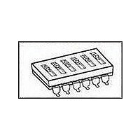
... Raised Type Flat actuator (Yellow) actuator (striker Standard (Yellow) color) SMT terminal DIP terminal No. of Quan- poles tity per stick A6T-1104 1 --- --- A6T-2104 2 76 A6S-2101 A6T-3104 3 55 A6S-3101 A6T-4104 4 42 A6S-4101 A6T-5104 5 35 A6S-5101 A6T-6104 6 28 A6S-6101 A6T-7104 7 25 A6S-7101 A6T-8104 8 22 ...
Page 2
... Operating force Flat/raised type 0.29 N min. {30 gf} Weight A6T: 0. poles), 0. poles), 0. poles), 0. poles), 0.96 g (10 poles) A6S: 0. poles), 0. poles), 0. poles), 0. poles), 0.87 g (10 poles) Dimensions Note: 1. All units are in millimeters unless otherwise indicated. 2. Unless otherwise specified, a tolerance of ± 0.4 mm applies to all dimensions. ...
Page 3
... Be sure to refer to General Precautions on pages for details on proper use. ALL DIMENSIONS SHOWN ARE IN MILLIMETERS. To convert millimeters into inches, multiply by 0.03937. To convert grams into ounces, multiply by 0.03527. Cat. No. A102-E1-02 Flat Actuator With Seal Tape Standard No. of poles 2 A6S-2101 3 A6S-3101 4 A6S-4101 5 A6S-5101 6 A6S-6101 7 ...
Page 4
... Preheating 60 to 120 40 max. Do not use reflow soldering for any models other than the A6S-H and A6H. Otherwise the plastic case may melt or deform. The soldering conditions and the temperature around the Switch may vary with the type of reflow bath. Check the temperature pro- file and confirm soldering conditions as well as the amount of heat applied to the Switch prior to soldering ...
Page 5
... The models for which washing are possible are shown in the fol- lowing table. Washable A6A, A6C, A6CV, A6D, A6DR, A6T (with seal tape), A6S-H (with seal tape), A6H (with seal tape) Non-washable A6R, A6RV, A6T (standard/raised actuator), A6S- H (standard/raised actuator), A6E, A6ER 2 ...
Page 6
... Precautions Note: All units are in millimeters unless otherwise indicated. Packing specifications ■ • A6S-H models with embossed taping specifications are shown below. +0.4 1.5 dia. −0.2 Perforations 16 ±0.15 2 ±0.15 B ±0.15 +0.4 (See A −0.2 note.) Note: The perforations along both sides are for Switch- es with 7 poles or more ...