A6S-3104 Omron, A6S-3104 Datasheet - Page 4
A6S-3104
Manufacturer Part Number
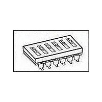
A6S-3104
Description
SWITCH DIP 3POS TOP ACT SMT
Manufacturer
Omron
Series
A6Sr
Specifications of A6S-3104
Circuit
SPST
Number Of Positions
3
Contact Rating @ Voltage
0.025A @ 24VDC
Actuator Type
Standard
Actuator Level
Raised
Mounting Type
Surface Mount
Orientation
Top Actuated
Washable
No
Contact Configuration
SPST
Contact Current Max
25mA
Switch Terminals
SMD Gull Wing
Lead Free Status / RoHS Status
Lead free / RoHS Compliant
Other names
A6S3104


Installation
I Internal Connections (Top View)
Precautions
I Circuit Design
Use the DIP Switch within the rated voltage and current ranges,
otherwise the DIP Switch may have a shortened life expectancy, radi-
ate heat, or burn out.
I Mounting
Do not operate the DIP Switch while mounting, soldering, or washing
the DIP Switch, otherwise the DIP Switch may deform due to the
heat of the solder, the DIP Switch may malfunction due to the pene-
tration of the washing agent, or the machine incorporating the DIP
Switch may operate or be set incorrectly.
An automatic insertion machine incorporating a body stopper is avail-
able for mounting the DIP Switch. When using an automatic insertion
machine incorporating a half-lead stopper to mount the DIP Switch,
make sure that the automatic insertion machine will not deform the
terminals of the DIP Switch, otherwise the improper insertion of the
DIP Switch may result.
I Soldering
Observe the following conditions when soldering the DIP Switch.
Automatic Soldering Bath
Soldering temperature:
Soldering time:
350°C at the tip of the soldering iron
3 s max. for a 1.6-mm thick, single-side
PCB
Reflow Soldering
Manual Soldering
Set the pins of the DIP Switch to OFF before soldering the DIP
Switch.
Before soldering the DIP Switch on a PCB, make sure that there is
no unnecessary space between the DIP Switch and PCB.
Before soldering the DIP Switch on a multilayer PCB, make sure that
the DIP Switch will not be deformed by the soldering heat on the pat-
tern or land of the multilayer PCB.
Do not solder the DIP Switch more than twice including rectification
soldering. An interval of five minutes is required between the first and
second solderings.
Make sure that there is no flux rise on the surface of the PCB.
Soldering temperature:
Soldering time:
DIP Switch
350°C at the tip of the soldering iron
3 s max. for a 1.6-mm thick, single-side
PCB
A6T/A6S
1193
Related parts for A6S-3104
Image
Part Number
Description
Manufacturer
Datasheet
Request
R

Part Number:
Description:
SWITCH DIP 3POS TOP ACT SMT
Manufacturer:
Omron
Datasheet:
Part Number:
Description:
SWITCH DIP 3POS TOP ACT SMT
Manufacturer:
Omron
Datasheet:

Part Number:
Description:
Dip Switch
Manufacturer:
Omron
Datasheet:
Part Number:
Description:
Dip Switch
Manufacturer:
Omron
Datasheet:
Part Number:
Description:
Tape And Reel Dipswitch
Manufacturer:
Omron
Datasheet:
Part Number:
Description:
Dip Switch
Manufacturer:
Omron
Datasheet:

Part Number:
Description:
Dip Switch
Manufacturer:
Omron
Datasheet:
Part Number:
Description:
SWITCH DIP 2POS TOP ACT GULLEAD
Manufacturer:
Omron
Datasheet:

Part Number:
Description:
SWITCH DIP 4POS TOP ACT GULLEAD
Manufacturer:
Omron
Datasheet:
Part Number:
Description:
SWITCH DIP 5POS TOP ACT GULLEAD
Manufacturer:
Omron
Datasheet:
Part Number:
Description:
SWITCH DIP 6POS TOP ACT GULLEAD
Manufacturer:
Omron
Datasheet:
Part Number:
Description:
SWITCH DIP 8POS TOP ACT GULLEAD
Manufacturer:
Omron
Datasheet:
Part Number:
Description:
SWITCH DIP SMT 2POS EXT ACTUAT
Manufacturer:
Omron
Datasheet:
Part Number:
Description:
SWITCH DIP SMT 4POS EXT ACTUAT
Manufacturer:
Omron
Datasheet:
Part Number:
Description:
SWITCH DIP SMT 5POS EXT ACTUAT
Manufacturer:
Omron
Datasheet: