MRF112 NKK Switches, MRF112 Datasheet - Page 2
MRF112
Manufacturer Part Number
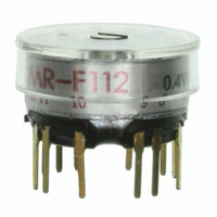
MRF112
Description
SW ROTARY SP 2-12POS PC
Manufacturer
NKK Switches
Series
MRr
Type
Rotaryr
Specifications of MRF112
Number Of Positions
2 ~ 12
Number Of Decks
1
Number Of Poles Per Deck
1
Circuit Per Deck
SP12T
Contact Rating @ Voltage
0.4VA @ 28VAC/DC
Actuator Type
Flush (Slotted)
Mounting Type
PCB, Through Hole
Termination Style
PC Pin
Orientation
Vertical
Angle Of Throw
30°
Body Style
Miniature
Current, Rating
0.1 A
Dielectric Strength
500 VAC
Mounting Hole Size
0.25 "
Number Of Poles
1
Termination
Solder
Voltage, Rating
28 VAC/VDC
No. Of Poles
1
No. Of Switch Positions
12
Contact Current Ac Max
100mA
Contact Current Dc Max
100mA
Contact Voltage Ac Max
28V
Contact Voltage Dc Max
28V
Svhc
No SVHC
Rohs Compliant
Yes
Lead Free Status / RoHS Status
Lead free / RoHS Compliant
Other names
360-2370
MRF112-RO
MRF112-RO
MRF112-RO
MRF112-RO


General Specifications
Electrical Capacity (Resistive Load)
Other Ratings
Materials & Finishes
Environmental Data
Installation
Processing
Standards & Certifications
NKK Switches
Common Contacts & Terminals:
Operating Temperature Range:
Soldering Time & Temperature:
Range of Operating Torque:
End Contacts & Terminals:
Cap Installation Force:
Insulation Resistance:
or CSA Certification:
Contact Resistance:
Dielectric Strength:
Movable Contacts:
Bushing/Housing:
Mounting Torque:
For MRF or MRK:
Mechanical Life:
Contact Timing:
UL Recognition
Stopper Plate:
Electrical Life:
Vibration:
Humidity:
Indexing:
Cleaning:
For MRA:
Shock:
Shaft:
Base:
Half-Inch Diameter Process Sealed Rotaries
250mA @ 125V AC
0.4VA maximum @ 28V AC/DC maximum
(Applicable Range 0.1mA ~ 0.1A @ 20mV ~ 28V)
Note: Find additional explanation of operating range in Supplement section.
10 milliohms maximum for MRA; 50 milliohms maximum for MRF & MRK
100 megohms minimum @ 500V DC
1,000V AC minimum for 1 minute minimum for MRA
500V AC minimum for 1 minute minimum for MRF & MRK
30,000 operations minimum
10,000 operations minimum
0.02 ~ 0.07Nm for MRA; 0.005 ~ 0.02Nm for MRF & MRK
Nonshorting (break-before-make)
MRA – self-cleaning, sliding contact; MRF & MRK – self-cleaning, rotary contactor disk
30°
Brass with nickel plating
Steel with zinc plating for MRA & MRK; polyamide cover with stopper for MRF
Zinc alloy with zinc plating
Copper with silver plating for MRA; phosphor bronze with gold plating for MRF & MRK
Brass with silver plating for MRA; phosphor bronze with gold plating for MRF & MRK
Brass with silver plating for MRA; phosphor bronze with gold plating for MRF & MRK
Diallyl phthalate for MRA; fiberglass reinforced polyamide for MRF & MRK
–10°C through +70°C (+14°F through +158°F)
90 ~ 95% humidity for 96 hours @ 40°C (104°F)
10 ~ 55Hz with peak-to-peak amplitude of 1.5mm traversing the frequency range
& returning in 1 minute; 3 right angled directions for 2 hours
50G (490m/s
.686Nm (6.08 lb
19.6 ~ 29.4N (4.41 ~ 6.61 lbf) for MRA & MRK
Wave Soldering for MRA: See Profile A in Supplement section.
Wave Soldering for MRF & MRK: See Profile B in Supplement section.
Manual Soldering for MRA: See Profile A in Supplement section.
Manual Soldering for MRF & MRK: See Profile B in Supplement section.
Automated cleaning recommended. Stopper plate, as well as washers for MRA & MRK, must be in
place to maintain automated cleaning. See Cleaning specifications in Supplement section.
MRA, MRF, & MRK models have not been tested for UL recognition or CSA certification.
These switches are designed for use in a low-voltage, low-current, logic-level circuit.
When used as intended in a logic-level circuit, the results do not produce hazardous energy.
2
) acceleration (tested in 3 right angled directions, with 3 shocks in each direction)
•
in)
Series MR
Related parts for MRF112
Image
Part Number
Description
Manufacturer
Datasheet
Request
R

Part Number:
Description:
Rotary Switches ROTARY SWITCH 1 POL 2 POS 3 PIN
Manufacturer:
Well Buying
Part Number:
Description:
Rotary Switches ROTARY SWITCH 1 POL 3 POS 4 PIN
Manufacturer:
Well Buying
Datasheet:
Part Number:
Description:
Rotary Switches ROTARY SWITCH 1 POL 8 POS 8 PIN
Manufacturer:
Well Buying
Datasheet:
Part Number:
Description:
Rotary Switches ROTARY SWITCH 1 POL 6 POS 7 PIN
Manufacturer:
Well Buying
Datasheet:
Part Number:
Description:
Rotary Switches ROTARY SWITCH 1 POL 4 POS 5 PIN
Manufacturer:
Well Buying
Datasheet:
Part Number:
Description:
Rotary Switches ROTARY SWITCH 1 POL 2 POS 8 PIN
Manufacturer:
Well Buying
Datasheet:

Part Number:
Description:
SW ROTARY DPDT BLK KNOB SLD LUG
Manufacturer:
NKK Switches
Datasheet:

Part Number:
Description:
SW ROTARY SP BLK KNOB TURRET
Manufacturer:
NKK Switches
Datasheet:

Part Number:
Description:
SW ROTARY SP BLK KNOB PC TURRET
Manufacturer:
NKK Switches
Datasheet:

Part Number:
Description:
SW ROTARY SP 2-12POS BLK KNOB PC
Manufacturer:
NKK Switches
Datasheet:

Part Number:
Description:
ON-OFF PLATE - SERIES -EMP
Manufacturer:
NKK Switches
Datasheet:

Part Number:
Description:
WRENCH SOCKET FOR KB SERIES PB
Manufacturer:
NKK Switches
Datasheet:

Part Number:
Description:
SWITCH TOGGLE DPST 25A SLDR 5PCS
Manufacturer:
NKK Switches
Datasheet:

Part Number:
Description:
SWITCH TOGGLE DPDT 15A SLDR 5PC
Manufacturer:
NKK Switches
Datasheet:

Part Number:
Description:
SWITCH TOGGLE 4PST 25A SLDR 5PCS
Manufacturer:
NKK Switches
Datasheet: