MRK206-CC NKK Switches, MRK206-CC Datasheet - Page 4
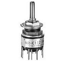
MRK206-CC
Manufacturer Part Number
MRK206-CC
Description
SW ROTARY ACTUATOR DP 2-6 POS
Manufacturer
NKK Switches
Series
MRr
Type
Half-Inch Process Sealed Rotariesr
Datasheet
1.AT433A.pdf
(6 pages)
Specifications of MRK206-CC
Number Of Positions
2 ~ 6
Number Of Decks
1
Number Of Poles Per Deck
2
Circuit Per Deck
DP6T
Contact Rating @ Voltage
0.4VA @ 28VAC/DC
Actuator Type
Knob
Mounting Type
Panel, PCB Through Hole
Termination Style
PC Pin
Orientation
Vertical
Angle Of Throw
30°
Index Angle
30 deg
Contact Style
Non Shorting
Contact Form
DP
Color
Black, Red
Contact Material
Phosphor Bronze
Contact Plating
Gold
Dielectric Strength
500 VoltsAC
Voltage Rating
28 VoltsAC/DC
Current Rating
0.4 Volt-Amp at 28 VoltsAC/DC
Actuator
Shaft Actuated, Low Profile with Knob
Cap Color
Black, Red
Contact Rating
0.4 Volt-Amp at 28 VoltsAC/DC
Voltage Rating Ac
28 Volts
Voltage Rating Dc
28 Volts
Total # Of Positions
5
Pole Throw Configuration
DP
Actuator Style
Shaft
Actuator Material
Brass
Current Rating (max)
0.1A
Illumination Type
Not Required
Ac Voltage Rating (max)
28VVAC
Dc Voltage Rating (max)
28VVDC
Mechanical Life
30000
Product Height (mm)
25.6mm
Product Depth (mm)
12.6mm
Product Length (mm)
12.6mm
Operating Temp Range
-10C to 70C
Mounting Style
Panel
Terminal Type
PC Pins
Lead Free Status / RoHS Status
Lead free / RoHS Compliant


Half-Inch Diameter Process Sealed Rotaries
Each switch is supplied with the stopper set for the maximum number of positions allowed for that model. Prior to installation,
the desired position setting should be made. Contact factory for continuous rotation.
1. Remove the protective cover from the switch body.
2. Turn the shaft counterclockwise to the extreme left by using a screwdriver.
3. Inside the cover is a magnifying lens which would be positioned over the
1. Using the actuator knob, turn the shaft
2. Remove the knob from the shaft and
3. Note the position numbers on the side
4. Tighten the nut (beveled side up) firmly
Pole
DP
SP
4P
number which is to be the maximum position used; when the cover is then
snapped into the switch, the projection beside the lens fits into the correct
hole for setting the stop.
counterclockwise to the extreme left. If
the shaft is not turned counterclockwise
to the extreme left, proper setting can-
not be achieved. At this extreme posi-
tion, the white line on the knob points
to the number 1 position shown on the
side of the switch.
loosen the nut far enough to allow rais-
ing the stopper plate, plus washer(s),
for resetting to the desired position.
of the switch; these correspond to the
terminal numbers and stopper holes.
Insert the stopper in the hole numbered
for the maximum desired number of
stop settings. Satisfactory switch func-
tioning cannot be assured if the stopper
plate is not properly positioned.
against the stopper plate.
MRA112
MRA206
MRA403
MRK112
MRK206
MRK403
MRF112
MRF206
MRF403
Model
MRK & MRA Models
Number of Positions
POSITION SETTING FOR MRA, MRF, & MRK MODELS
2–12
2–12
2–12
2–6
2–6
2–6
2–3
2–3
2–3
MRF Models
Stopper Settings
2, 3, 4, . . . 12
2, 3, 4, . . . 12
2, 3, 4, . . . 12
2, 3, 4, 5, 6
2, 3, 4, 5, 6
2, 3, 4, 5, 6
POLES & CIRCUITS
2, 3
2, 3
2, 3
1 C
11
12
www.nkk.com
Number of Terminals
1 COM, 12 LOAD
1 COM, 12 LOAD
1 COM, 12 LOAD
2 COM, 12 LOAD
2 COM, 12 LOAD
2 COM, 12 LOAD
4 COM, 12 LOAD
4 COM, 12 LOAD
4 COM, 12 LOAD
Packaged Loose with Each Switch:
Standard Mounting Hardware
Metal Washer (MRA)
Factory Assembled:
Rubber Ring (MRK)
Rubber Washer
Hex Face Nut
Stopper Plate
Locking Ring
Lockwasher
Hex Nut
Protective Cover
1 2 3 4 5 6 7 8 9 10 11 12
1 2 3 4 5 6 1
1 2 3 1
A
Series MR
1 C
A
12
Schematics
2 3 1
B
A
Lens
Projection
1
2 3 4 5 6
2 3 1
C
12
11
B
9
2 3
D
G19
G
Related parts for MRK206-CC
Image
Part Number
Description
Manufacturer
Datasheet
Request
R

Part Number:
Description:
Rotary Switches DP 6 POSITION LOW SHAFT ACTUATOR PC
Manufacturer:
NKK Switches
Datasheet:
Part Number:
Description:
Rotary Switches DP 2-6 POSITIONS 250mA WHITE KNOB PC
Manufacturer:
NKK Switches
Datasheet:
Part Number:
Description:
Rotary Switches DP 6 POS LOW SHAFT ACTR PC RED TIP KNOB
Manufacturer:
NKK Switches
Datasheet:

Part Number:
Description:
SW ROTARY DP 2-6POS PC
Manufacturer:
NKK Switches
Datasheet:
Part Number:
Description:
SWITCH ROTARY DP6T PC MNT
Manufacturer:
NKK Switches
Datasheet:
Part Number:
Description:
SW ROTARY DP WHT TIP SM KNOB PC
Manufacturer:
NKK Switches
Datasheet:
Part Number:
Description:
Rotary Switches LO PRO SHFT 2-6 POS
Manufacturer:
NKK Switches
Datasheet:

Part Number:
Description:
SW ROTARY DP 2-6POS BLK KNOB PC
Manufacturer:
NKK Switches
Datasheet:

Part Number:
Description:
Rocker Switches & Paddle Switches High In-rush Rated Rocker Switch
Manufacturer:
NKK Switches
Datasheet:
Part Number:
Description:
Rocker Switches & Paddle Switches High In-rush Rated Rocker Switch
Manufacturer:
NKK Switches
Datasheet:
Part Number:
Description:
Rocker Switches & Paddle Switches High In-rush Rated Rocker Switch
Manufacturer:
NKK Switches
Datasheet:
Part Number:
Description:
Rocker Switches & Paddle Switches High In-rush Rated Rocker Switch
Manufacturer:
NKK Switches
Datasheet:

Part Number:
Description:
Pushbutton Switches SPST ON(OFF) 15/32'
Manufacturer:
NKK Switches
Datasheet:

Part Number:
Description:
Pushbutton Switches SPST OFF(ON) 15/32'
Manufacturer:
NKK Switches
Datasheet:

Part Number:
Description:
Pushbutton Switches ON(OFF) NORM CLSD 3A RED PLNGR LUG 15/32
Manufacturer:
NKK Switches
Datasheet: