V-15G5-1C26-K Omron, V-15G5-1C26-K Datasheet - Page 5
V-15G5-1C26-K
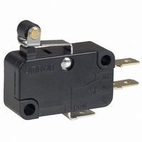
Manufacturer Part Number
V-15G5-1C26-K
Description
SWITCH ROLLER SPDT 15A .187QC
Manufacturer
Omron
Series
Vr
Type
Snap Actionr
Specifications of V-15G5-1C26-K
Circuit
SPDT
Switch Function
On-Mom
Contact Rating @ Voltage
15A @ 250VAC
Actuator Type
Lever, Roller
Mounting Type
Chassis Mount
Termination Style
Quick Connect - .187" (4.7mm)
Operating Force
480gf
Contact Form
SPDT
Contact Rating
15 Amps at 250 Volts
Actuator
Hinge Roller Lever
Microswitch Type
Snap Action
Actuator Style
Hinge Roller Lever
Operating Force Max
400gf
Contact Voltage Ac Nom
250V
Contact Voltage Dc Nom
250V
Contact Current Max
15A
Lead Free Status / RoHS Status
Lead free / RoHS Compliant
Lead Free Status / RoHS Status
Lead free / RoHS Compliant, Lead free / RoHS Compliant
Other names
SW136
V15G51C26K
V15G51C26K


V
■
Note:
■
Consult your OMRON sales representative for specific models with standard approvals.
UL1054 (File No. E41515)/CSA C22.2 No. 55 (File No. LR21642)
EN61058-01 (File No. 40025231, VDE approval)
Testing conditions: 5E4 (50,000 operations), for models of V-21: T80 (0°C to 80°C), for models of V-16: T105 (0°C to 105°C)
Operating speed
Operating frequency
Insulation resistance
Contact resistance
(initial value)
Dielectric strength
(see note 2)
Vibration resistance
(see note 3)
Shock resistance
(see note 3)
Durability
(see note 4)
Degree of protection
Degree of protection against
electric shock
Proof tracking index (PTI)
Ambient operating tempera-
ture
Ambient operating humidity
Weight
125 VAC
250 VAC
125 VDC
250 VDC
250 VAC
Characteristics
Approved Standards
Rated voltage
Rated voltage
1. The data given above are initial values.
2. The dielectric strength values shown in the table are for models with a Separator.
3. For the pin plunger models, the above values apply for use at both the free position and total travel position. For the lever models,
4. For testing conditions, contact your OMRON sales representative.
they apply at the total travel position.
21 A, 1/2 HP
0.6 A
0.3 A
20 (4) A
0.1 mm to 1 m/s (pin plunger models)
Mechanical:600 operations/min max. (pin plunger models)
Electrical:60 operations/min max.
100 MΩ min. (at 500 VDC)
15 mΩ max.
1,000 VAC, 50/60 Hz for 1 min between terminals of the same polarity
V-21 and V-16 models: 2,000 VAC, 50/60 Hz for 1 min between current-carrying metal parts and
ground, and between each terminal and non-current-carrying metal parts
V-15 and V-10 models: 1,500 VAC, 50/60 Hz for 1 min between current-carrying metal parts and
ground, and between each terminal and non-current-carrying metal parts
Malfunction: 10 to 55 Hz, 1.5-mm double amplitude
Destruction: 1,000 m/s
Malfunction: V-21/V-16/V-15: 300 m/s
Mechanical: 50,000,000 operations min. (60 operations/min)
Electrical:
IEC IP40
Class I
175
–25°C to 80°C (at ambient humidity of 60% max.) (with no icing or condensation)
–25°C to 150°C for heat-resistive model (at ambient humidity of 60% max.) (with no icing or conden-
sation)
85% max. (for 5°C to 35°C)
Approx. 6.2 g (pin plunger models)
V-21
V-21
V-21/V-16/V-15: 100,000 operations min. (30 operations/min)
V-10:
V-10:
16 A, 1/2 HP
0.6 A
0.3 A
16 (4) A
2
{approx. 100G} max.
200 m/s
(V-15 heat resistive: 20,000 operation min. (30 operations/min))
300,000 operations min. (30 operations/min)
(V-10 heat resistive: 50,000 operation min. (30 operations/min))
V-16
V-16
2
2
{approx. 30G} max.
{approx. 20G} max.
15 A, 1/2 HP
0.6 A
0.3 A
V-15
10 A, 1/3 HP
0.6 A
0.3 A
V-10
V
5
Related parts for V-15G5-1C26-K
Image
Part Number
Description
Manufacturer
Datasheet
Request
R

Part Number:
Description:
SWITCH ROLLER SPDT 15A .187QC
Manufacturer:
Omron
Datasheet:

Part Number:
Description:
MINIATURE BASIC SWITCH
Manufacturer:
Omron
Datasheet:

Part Number:
Description:
MINIATURE BASIC SWITCH
Manufacturer:
Omron
Datasheet:

Part Number:
Description:
MINIATURE BASIC SWITCH
Manufacturer:
Omron
Datasheet:

Part Number:
Description:
MINIATURE BASIC SWITCH
Manufacturer:
Omron
Datasheet:
Part Number:
Description:
MINIATURE BASIC SWITCH
Manufacturer:
Omron
Datasheet:

Part Number:
Description:
MICRO SWITCH, PIN PLUNGER, SPDT 15A 250V
Manufacturer:
Omron
Datasheet:

Part Number:
Description:
SWITCH BASIC SPDT 15A 200GF
Manufacturer:
Omron
Datasheet:
Part Number:
Description:
SWITCH BASIC SPST 15A .187QC
Manufacturer:
Omron
Datasheet:
Part Number:
Description:
SWITCH BASIC SPDT 15A 400GF
Manufacturer:
Omron
Datasheet:
Part Number:
Description:
SWTCH MINI SPST-NC 15A PIN PLNGR
Manufacturer:
Omron
Datasheet:
Part Number:
Description:
MINIATURE BASIC SWITCH
Manufacturer:
Omron
Datasheet:
Part Number:
Description:
MINIATURE BASIC SWITCH
Manufacturer:
Omron
Datasheet: