J-7-V Omron, J-7-V Datasheet - Page 2
J-7-V
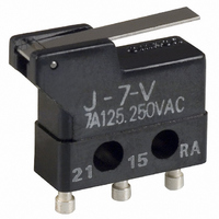
Manufacturer Part Number
J-7-V
Description
SWITCH SHORT LVR SPDT 7A TURRET
Manufacturer
Omron
Series
Jr
Type
Ultra Subminiature Basic Switchr
Specifications of J-7-V
Circuit
SPDT
Switch Function
On-Mom
Contact Rating @ Voltage
7A @ 250VAC
Actuator Type
Lever, Straight
Mounting Type
Chassis Mount
Termination Style
Solder Turret
Operating Force
50gf
Microswitch Type
Ultra Subminiature
Actuator Style
Hinge Lever
Operating Force Max
50gf
Contact Voltage Ac Nom
250V
Contact Voltage Dc Nom
250V
Contact Current Max
7A
Contact Form
SPDT
Contact Rating
7 Amps at 250 Volts
Actuator
Lever
Lead Free Status / RoHS Status
Lead free / RoHS Compliant
Lead Free Status / RoHS Status
Lead free / RoHS Compliant, Lead free / RoHS Compliant
Other names
J7V
SW814
Z2167
Z2167
SW814
Z2167
Z2167


J
Specifications
■
Note:
■
Note:
■
Consult your OMRON sales representative for specific models
with standard approvals.
UL508 (File No. E41515)/
CSA C22.2 No. 55 (File No. LR21642)
2
125 VAC
250 VAC
Operating speed
Operating frequency
Insulation resistance
Contact resistance (initial value)
Dielectric strength
Vibration resistance (see note 2)
Shock resistance (see note 2, 3)
Durability (see note 4)
Degree of protection
Degree of protection against electric
shock
Proof tracking index (PTI)
Ambient operating temperature
Ambient operating humidity
Weight
125 VAC
250 VAC
Ratings
Characteristics
Approved Standards
Rated voltage
Rated voltage
The ratings values apply under the following test conditions:
Ambient temperature: 20±2°C
Ambient humidity: 65±5%
Operating frequency: 30 operations/min
1. The data given above are initial values.
2. Malfunction: 1 ms max.
3. For the pin plunger models, the values are at the free position and total travel position. For the lever models, they are at the total
4. For testing conditions, consult your OMRON sales representative.
travel position.
7 A
7 A
J-7
7 A
7 A
Resistive load
0.05 mm to 1 m/s (pin plunger models)
Mechanical: 400 operations/min max.
Electrical:
100 MΩ min. (at 500 VDC)
15 mΩ max.
600 VAC, 50/60 Hz for 1 min between terminals of the same polarity
1,500 VAC, 50/60 Hz for 1 min between each terminal and non-current-carrying metal part and
between current-carrying metal part and ground.
Malfunction: 10 to 55 Hz, 1.5-mm double amplitude
Destruction: 1,000 m/s
Malfunction: 200 m/s
Mechanical: 10,000,000 operations min. (60 operations/min)
Electrical:
IEC IP40
Class I
175
–10°C to 80°C (at ambient humidity of 60% max.) (with no icing or condensation)
85% max. (for 5°C to 35°C)
Approx. 1 g (pin plunger models)
30 operations/min max.
50,000 operations min. (30 operations/min)
2
{approx. 20G} max. (pin plunger models)
2
{approx. 100G} max.
■
■
Contact
Inrush
current
Minimum applicable load
Contact Specifications
Contact Form
Specification
Material
Gap (standard value)
NC
NO
SPDT
Rivet
Silver plated
Gold plated
0.35 mm
15 A max.
7 A max.
30 mA at 5 VDC
J
Related parts for J-7-V
Image
Part Number
Description
Manufacturer
Datasheet
Request
R

Part Number:
Description:
SWITCH BASIC SPDT 7A TURRET
Manufacturer:
Omron
Datasheet:

Part Number:
Description:
SWITCH ROLLER LVR SPDT 7A TURRET
Manufacturer:
Omron
Datasheet:

Part Number:
Description:
SWITCH HINGE LVR SPDT 7A TURRET
Manufacturer:
Omron
Datasheet:

Part Number:
Description:
MICRO SWITCH, ROLLER LEVER, SPDT 7A 250V
Manufacturer:
Omron
Datasheet:

Part Number:
Description:
SWITCH LONG LEVER SPDT 7A TURRET
Manufacturer:
Omron
Datasheet:

Part Number:
Description:
SUBMINIATURE BASIC SWITCH
Manufacturer:
Omron
Datasheet:

Part Number:
Description:
G6S-2GLow Signal Relay
Manufacturer:
Omron Corporation
Datasheet:
Part Number:
Description:
Compact, Low-cost, SSR Switching 5 to 20 A
Manufacturer:
Omron Corporation
Datasheet:
Part Number:
Description:
Manufacturer:
Omron Corporation
Datasheet:
Part Number:
Description:
Manufacturer:
Omron Corporation
Datasheet:
Part Number:
Description:
Manufacturer:
Omron Corporation
Datasheet: