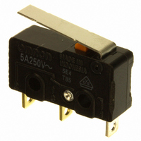
SS-5GL-F Omron, SS-5GL-F Datasheet

SS-5GL-F
Specifications of SS-5GL-F
SS-5GLF
SS5GLF
SW1007
Available stocks
Related parts for SS-5GL-F
SS-5GL-F Summary of contents
Page 1
... N {50 gf} (0 -E: 0.25 N {25 gf} (0.1 A) Note: These values are for pin plunger models. 4. Contact Form None: SPDT -2: SPST-NC -3: SPST-NO 5. Terminals None: Solder terminals T: Quick-connect terminals (#110) D: PCB terminals (see note 2) 6. Special Code None: Standard (85°C) -T: Heat resistive (120° ...
Page 2
... SS-5-F-3D SS-01-F-3D --- SS-01-E --- SS-01-E-2 --- SS-01-E-3 --- SS-01-ET --- SS-01-E-2T --- SS-01-E-3T --- SS-01-ED --- SS-01-E-2D --- SS-01-E-3D SS-5GL SS-01GL SS-5GL-2 SS-01GL-2 SS-5GL-3 SS-01GL-3 SS-5GLT SS-01GLT SS-5GL-2T SS-01GL-2T SS-5GL-3T SS-01GL-3T SS-5GLD SS-01GLD SS-5GL-2D SS-01GL-2D SS-5GL-3D SS-01GL-3D SS-5GL-F SS-01GL-F SS-5GL-F-2 SS-01GL-F-2 SS-5GL-F-3 SS-01GL-F-3 SS-5GL-FT SS-01GL-FT SS-5GL-F-2T SS-01GL-F-2T SS-5GL-F-3T SS-01GL-F-3T ...
Page 3
... SPST-NC --- CPST-NO --- SPDT 0. gf} --- SPST-NC --- CPST-NO --- SPDT --- SPST-NC --- CPST-NO --- SPDT --- SPST-NC --- CPST-NO --- 0.1 A SS-5GL-FD SS-01GL-FD SS-5GL-F-2D SS-01GL-F-2D SS-5GL-F-3D SS-01GL-F-3D --- SS-01GL-E --- SS-01GL-E-2 --- SS-01GL-E-3 --- SS-01GL-ET --- SS-01GL-E-2T --- SS-01GL-E-3T --- SS-01GL-ED --- SS-01GL-E-2D --- SS-01GL-E-3D SS-5GL13 SS-01GL13 SS-5GL13-2 SS-01GL13-2 SS-5GL13-3 SS-01GL13-3 SS-5GL13T SS-01GL13T SS-5GL13-2T SS-01GL13-2T SS-5GL13-3T SS-01GL13-3T ...
Page 4
... SS-5GL2-F SS-01GL2-F SS-5GL2-F-2 SS-01GL2-F-2 SS-5GL2-F-3 SS-01GL2-F-3 SS-5GL2-FT SS-01GL2-FT SS-5GL2-F-2T SS-01GL2-F-2T SS-5GL2-F-3T SS-01GL2-F-3T SS-5GL2-FD SS-01GL2-FD SS-5GL2-F-2D SS-01GL2-F-2D SS-5GL2-F-3D SS-01GL2-F-3D --- SS-01GL2-E --- SS-01GL2-E-2 --- SS-01GL2-E-3 --- SS-01GL2-ET --- SS-01GL2-E-2T --- SS-01GL2-E-3T --- SS-01GL2-ED --- SS-01GL2-E-2D --- SS-01GL2-E- 0.1 A SS-5-T SS-01-T SS-5T-T SS-01T-T SS-5D-T SS-01D-T SS-5GL-T SS-01GL-T SS-5GLT-T SS-01GLT-T SS-5GLD-T SS-01GLD-T SS-5GL13-T ...
Page 5
... OF 0.49 N {50 gf}: OF 0.25 N {25 gf}: Dielectric strength 1,000 VAC (600 VAC for SS-01 models), 50/60 Hz for 1 min between terminals of the same polarities (see note 2) 1,500 VAC, 50/60 Hz for 1 min between current-carrying metal part and ground, and between each ter- minal and non-current-carrying metal part Vibration resistance Malfunction Hz, 1 ...
Page 6
... VAC Testing conditions: 5E4 (50,000 operations); T85 (0°C to 85°C). Dimensions Note: All units are in millimeters unless otherwise indicated. Terminals ■ Terminal plate thickness is 0.5 mm for all models. Solder Terminals 2.9 6.4 1.6 3.2 8.8 7.3 COM Three, 1.6-dia. holes terminal 6 ...
Page 7
... N {50 gf} 0.16 N {16 gf} 0. gf} 0. gf} 1.2 mm 1.2 mm 0.8 mm 0.8 mm 3.2 6.4 3.2 Three, 1.6 dia. 6.4 SS-5-F SS-01-E SS-01-F 0.25 N {25 gf} 0. gf} 0.5 mm 0.5 mm 0.1 mm 3.6 6.4 Three, 1.6 dia. 3.2 6.4 SS-5GL-F SS-01GL-E SS-01GL-F 0. gf} 0. gf} (reference value) 1 ...
Page 8
... Note: Stainless-steel spring lever SS-5GL13-F SS-01GL13-E SS-01GL13-F 0. gf} 0. gf} (reference value) 1.2 mm 0.8 mm 4.8 dia. × 3.2 (see note 2) 6.4 Three, 1.6 dia. 3.2 6.4 1. Stainless-steel spring lever Note: 2. Polyacetal resin roller SS-5GL2-F SS-01GL2-E SS-01GL2-F 0. gf} 0. gf} (reference value) 1 ...
Page 9
... The minimum applicable load is the N-level reference value. This value indicates the malfunction reference level for the reliability level of 60% (λ 60). The equation, λ 0.5×10 indicates that the estimated malfunction rate is less than 1/ 2,000,000 operations with a reliability level of 60%. Operating range ...


