D2SW-P01D Omron, D2SW-P01D Datasheet - Page 5
D2SW-P01D
Manufacturer Part Number
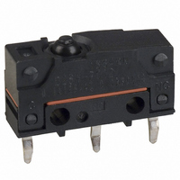
D2SW-P01D
Description
SWITCH BASIC SPDT .1A PCB
Manufacturer
Omron
Series
D2SW-Pr
Type
Basic/Snap Actionr
Specifications of D2SW-P01D
Circuit
SPDT
Switch Function
On-Mom
Contact Rating @ Voltage
0.1A @ 30VDC
Actuator Type
Round (Pin Plunger)
Mounting Type
Through Hole
Termination Style
PC Pin
Operating Force
183gf
Microswitch Type
Subminiature
Actuator Style
Pin Plunger
Operating Force Max
1.8N
Contact Voltage Ac Nom
125V
Contact Voltage Dc Nom
30V
Contact Current Max
100mA
Contact Form
SPDT
Contact Rating
0.1 Amp at 30 Volts
Actuator
Plunger, Pin
Ingress Protection
IP67, Watertight
Lead Free Status / RoHS Status
Lead free / RoHS Compliant
Lead Free Status / RoHS Status
Lead free / RoHS Compliant, Lead free / RoHS Compliant
Other names
D2SWP01D
SW804
Z2122
Z2122
SW804
Z2122
Z2122
Available stocks
Company
Part Number
Manufacturer
Quantity
Price


Precautions
Be sure to read the precautions and information common to all Snap Action and Detection Switches, contained in the Technical User’s Guide,
“Snap Action Switches, Technical Information” for correct use.
■ Correct Use
Mounting
Turn OFF the power supply before mounting or removing the Switch,
wiring, or performing maintenance or inspection. Failure to do so may
result in electric shock or burning.
Mount the Switch onto a flat surface. Mounting on an uneven surface
may cause deformation of the Switch, resulting in faulty operation or
damage.
Operating Body
Use an operating body with low frictional resistance and of a shape
that will not interfere with the sealing rubber, otherwise the plunger
may be damaged or the sealing may deteriorate.
With the pin plunger models, set the Switch so that the plunger can
be pushed in from directly above. Since the plunger is covered with a
rubber cap, applying a force from lateral directions may cause dam-
age to the plunger or reduction in the sealing capability
.
Handling
Do not handle the Switch in a way that may cause damage to the
sealing rubber. When handling the Switch, ensure that uneven pres-
sure or, as shown in the following diagram, pressure in a direction
other than the operating direction is not applied to the Actuator, oth-
erwise the Actuator or Switch may be damaged, or durability may be
decreased.
Wiring Molded Lead Wire Models
When wiring molded lead wire models, ensure that there is no weight
on the wire or that there are no sharp bends near the parts where the
wire is drawn out. Otherwise, damage to the Switch or deterioration
in the sealing may result.
Incorrect
Correct
Incorrect
Sealed Subminiature Basic Switch
Operating Stroke Setting
Set the operating stroke so that the actuator is completely disen-
gaged when the switch is in the free position (FP), and is pushed to a
point between 60% and 90% of the OT distance after the switch is
operated.
Insufficient or excessive pushing of the actuator may result in
decreased switch durability or damage to the switch.
Using Micro Loads
Using a model for ordinary loads to switch microloads may result in
faulty operation. Instead, use the models that are designed for
microloads and that operate in the following range;
However, even when using microload models within the operating
range shown above, if inrush current or inductive voltage spikes
occur when the contact is opened or closed, then contact wear may
increase and so decrease the service life. Therefore, insert a contact
protection circuit where necessary.
30
24
12
5
0
0.1
Inoperable
range
0.16mA
1mA
Operating range for
micro load models
D2SW-P01
1
10
26mA
D2SW-P
100mA 160mA
100mA
100
Current (mA)
Operating
range for
general-load
models
D2SW-P2
1,000
205
Related parts for D2SW-P01D
Image
Part Number
Description
Manufacturer
Datasheet
Request
R

Part Number:
Description:
Sealed Subminiature Basic Switch
Manufacturer:
Omron Corporation
Datasheet:

Part Number:
Description:
SWITCH BASIC SPDT 2A .110QC
Manufacturer:
Omron
Datasheet:

Part Number:
Description:
SWITCH SIM ROLLER SPDT 2A SLDR
Manufacturer:
Omron
Datasheet:

Part Number:
Description:
SWITCH SIM ROLL SPDT .1A .110QC
Manufacturer:
Omron
Datasheet:

Part Number:
Description:
SWITCH SIM ROLLER SPDT .1A PCB
Manufacturer:
Omron
Datasheet:

Part Number:
Description:
SWITCH ROLLER LEVER SPDT 2A SLDR
Manufacturer:
Omron
Datasheet:
Part Number:
Description:
SWITCH SIM ROLLER SPDT .1A PCB
Manufacturer:
Omron
Datasheet:
Part Number:
Description:
SWITCH BASIC SPDT .1A .110QC
Manufacturer:
Omron
Datasheet:

Part Number:
Description:
SWITCH SIM ROLLER SPDT 2A WIRE
Manufacturer:
Omron
Datasheet:
Part Number:
Description:
SWITCH SIM ROLLER SPDT .1A WIRE
Manufacturer:
Omron
Datasheet:

Part Number:
Description:
Miniature Basic Switch
Manufacturer:
Omron
Datasheet:
Part Number:
Description:
SUBMINIATURE BASIC SWITCH
Manufacturer:
Omron
Datasheet:
Part Number:
Description:
Subminiature Basic Switch
Manufacturer:
Omron
Datasheet:
Part Number:
Description:
Subminiature Basic Switch
Manufacturer:
Omron
Datasheet:
Part Number:
Description:
Miniature Basic Switch
Manufacturer:
Omron
Datasheet: