WGLA1A01AA1A Honeywell Sensing and Control, WGLA1A01AA1A Datasheet - Page 18
WGLA1A01AA1A
Manufacturer Part Number
WGLA1A01AA1A
Description
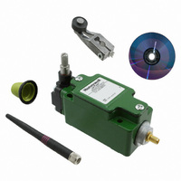
SW ROTARY STNDRD W/NYLON ROLLER
Manufacturer
Honeywell Sensing and Control
Series
WGLAr
Specifications of WGLA1A01AA1A
Circuit
SPDT
Switch Function
On-Mom
Actuator Type
Side Rotary
Mounting Type
Panel Mount, Wireless
Termination Style
Antenna, 2.4 GHz Radio
Actuator Style
Side Rotary
Operating Force Max
9.7N
Contact Voltage Dc Max
3.6V
Lead Free Status / RoHS Status
Lead free / RoHS Compliant
Contact Rating @ Voltage
-
Operating Force
-
Lead Free Status / RoHS Status
Lead free / RoHS Compliant, Lead free / RoHS Compliant
Other names
480-3318


Limitless™ WGLA Series
Pairing is required to initiate and establish an RF communication link between each single WGLA and a single
WPMM. The WGLA will be shipped from the factory with two identification labels (1) that are recommended to be
completed and applied to the WGLA housing during the pairing mode. As there are up to 16 WGLAs that can be
paired to a single WPMM, these labels will be used to identify the WGLA switch in the sequence of #1 to #16. The
initial WGLA switch paired to the WPMM will be Sequence #1; the second WGLA paired will be Sequence #2 and so
on. If replacing a WGLA switch that has been purged (see section 6.5 of the WPMM Installation and Technical
Manual), identify the correct replacement Sequence # on the identification labels.
The battery will need to be activated in the WGLA and proper power applied to the WPMM (green
illuminated) before proceeding with this pairing procedure. Once the pairing is completed, the WGLA selected will
only communicate with the WPMM it was paired to and no other device.
Step
14
5.3 Pairing Mode
1
2
3
4
5
6
7
8
Honeywell Sensing and Control
Action
Completely read this procedure before starting in order to understand the timing of events that need to be
performed.
WGLA: Remove (if required) the two screws
the function button
WPMM: Press the Function button
eight seconds at which time the green
function button immediately as it has entered the pairing mode.
WGLA: Within a 30 second interval of Step 3, depress the WGLA switch function button
and hold depressed for more than one second and less than 12 seconds at which time the orange
turns on. While in pairing mode, the orange led will flash on for 100 ms every second. The orange
flashes three times 100 ms on, 100 ms off when pairing succeeds. If pairing does not succeed, the orange
WPMM: Successful pairing will be indicated by the green
flash and remaining on for a few seconds before turning off. A short buzzer beep will also occur.
To confirm proper pairing between the WGLA and WPMM, actuate the WGLA, and the red LED
illuminate along with a buzzer sound.
Record the WGLA Sequence # on identification labels
locations (See Figure 7).
Repeat Steps 2-7 to add additional WGLA switches. Up to 16 WGLAs can be paired to a single WPMM.
ATTENTION
ATTENTION
ATTENTION
The operation and LED functions for the WPMM are visually depicted and described in Section 5.4.
This file is also located as a separate file on this CD or at www.honeywell.com/sensing.
The operation and LED functions for the WPMM are visually depicted and described in Section 5.4.
This file is also located as a separate file on this CD or at www.honeywell.com/sensing.
The purging of a WGLA per Section 5.4 is required when a previously paired WGLA is desired to be
paired again.
LED will turn off and user will need to repeat steps starting with Step 3.
to be used in Step 4.
on WPMM (See Figure 5) for more than four seconds and less than
and amber
on the housing cover (See Figure 4) of the WGLA and locate
LEDs will be flashing which indicates to release the
and apply to the WGLA housing in desired
and amber
LEDs (See Figure 5) ceasing to
Issue 2
50051863
(See Figure 6)
LED
should
LED
LED
Related parts for WGLA1A01AA1A
Image
Part Number
Description
Manufacturer
Datasheet
Request
R

Part Number:
Description:
SERIES 942 SEPARATE COMPLETE SENSOR WITH HEAD AND CONTROL BOX, 3000 MM [118.0 IN] SCAN DISTANCE, TWO ANALOG OUTPUTS (0 VDC TO 10 VDC AND 4 MA TO 20 MA) , TWO SWITCHING OUTPUTS PNP AND DIGITAL LINK
Manufacturer:
Honeywell Sensing and Control
Part Number:
Description:
SERIES 942 SEPARATE COMPLETE SENSOR WITH HEAD AND CONTROL BOX, 900 MM [35.0 IN] SCAN DISTANCE, TWO ANALOG OUTPUTS (0 VDC TO 10 VDC AND 4 MA TO 20 MA) , TWO SWITCHING OUTPUTS PNP AND DIGITAL LINK
Manufacturer:
Honeywell Sensing and Control
Part Number:
Description:
SERIES 942 SEPARATE COMPLETE SENSOR WITH HEAD AND CONTROL BOX, 1500 MM [59.0 IN] SCAN DISTANCE, TWO ANALOG OUTPUTS (0 VDC TO 10 VDC AND 4 MA TO 20 MA) , TWO SWITCHING OUTPUTS PNP AND DIGITAL LINK
Manufacturer:
Honeywell Sensing and Control
Part Number:
Description:
SERIES 942 SEPARATE CONTROL BOX, 3000 MM [118.0 IN] SCAN DISTANCE, TWO ANALOG OUTPUTS (0 VDC TO 10 VDC AND 4 MA TO 20 MA) , TWO SWITCHING OUTPUTS PNP AND DIGITAL LINK, TO USE WITH 942 OR 947 SENSOR HE
Manufacturer:
Honeywell Sensing and Control
Part Number:
Description:
100FW SERIES, SHIELDED 3-WIRE DC SINKING (NPN), N.O. PROXIMITY SENSOR, 0.625 IN CYLINDRICAL HOUSING , 20 GA, MIL-W-16878/4 WIRE. NOMINAL SENSING DISTANCE OF 2,41 MM ±
Manufacturer:
Honeywell Sensing and Control
Part Number:
Description:
100FW SERIES, SHIELDED 3-WIRE DC SINKING (NPN), N.O. PROXIMITY SENSOR, 0.625 IN CYLINDRICAL HOUSING , CONNECTOR VERSION MATES WITH MS3116-10-6S. NOMINAL SENSING DISTANCE OF 2,41 MM ±
Manufacturer:
Honeywell Sensing and Control
Part Number:
Description:
HyCal Sensing Products
Manufacturer:
Honeywell Sensing and Control
Part Number:
Description:
200FW SERIES, SHIELDED 3-WIRE DC SINKING (NPN), N.O. PROXIMITY SENSOR, 0.625 IN CYLINDRICAL HOUSING , CONNECTOR VERSION MATES WITH MS3116-8-4S. NOMINAL SENSING DISTANCE OF 2,4 MM TO 11,4 MM [.09 IN
Manufacturer:
Honeywell Sensing and Control
Part Number:
Description:
FF-SRL SERIES, PRESENCE SENSING DEVICE INITIATION MODULE, 24 VDC
Manufacturer:
Honeywell Sensing and Control
Part Number:
Description:
HyCal Sensing Products
Manufacturer:
Honeywell Sensing and Control
Part Number:
Description:
HyCal Sensing Products
Manufacturer:
Honeywell Sensing and Control
Part Number:
Description:
HyCal Sensing Products
Manufacturer:
Honeywell Sensing and Control
Part Number:
Description:
SERIES 942 SEPARATE SENSOR HEAD, 1500 MM [59.0 IN] SCAN DISTANCE, STAINLESS STEEL M30, CONNECTOR, TO USE WITH 942-M0A CONTROL BOX
Manufacturer:
Honeywell Sensing and Control