SS-5GL2-F Omron, SS-5GL2-F Datasheet - Page 6
SS-5GL2-F
Manufacturer Part Number
SS-5GL2-F
Description
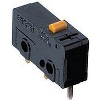
SWITCH BASIC SPDT 5A SOLDER
Manufacturer
Omron
Series
SSr
Type
Basicr
Specifications of SS-5GL2-F
Circuit
SPDT
Switch Function
On-Mom
Contact Rating @ Voltage
5A @ 125VAC
Actuator Type
Lever, Roller
Mounting Type
Chassis Mount
Termination Style
Solder Lug
Operating Force
16gf
Microswitch Type
Subminiature
Actuator Style
Hinge Roller Lever
Operating Force Max
16gf
Contact Voltage Ac Nom
250V
Contact Current Max
5A
Switch Terminals
Solder Lug
Circuitry
SPDT
Body Style
Subminiature
Contact Form
SPDT
Current, Rating
5/4 AAC/ADC
Dielectric Strength
1500 VAC
Force, Operating
16 g
Mounting Hole Size
2.4 mm
Number Of Poles
1
Operation
Snap Action
Standards
UL Recognized, CSA Certified
Temperature Rating
-25 to +85 °C
Termination
Solder
Voltage, Rating
125/30 VAC/VDC
Actuator
Roller Lever
Contact Rating
5 Amps at 125 Volts, 4 Amps at 30 Volts
Lead Free Status / RoHS Status
Lead free / RoHS Compliant
Lead Free Status / RoHS Status
Lead free / RoHS Compliant, Lead free / RoHS Compliant
Other names
SS5GL2F


SS
■
Consult your OMRON sales representative for specific models
with standard approvals.
UL1054 (File No. E41515)/CSA C22.2 No. 55 (File
No. LR21642)
EN61058-1 (File No. 129246 for SS-5, 125256 for
SS-10, VDE approval)
Testing conditions: 5E4 (50,000 operations); T85 (0°C to 85°C).
Dimensions
Note:
■
Terminal plate thickness is 0.5 mm for all models.
■
6
COM
terminal
(C)
Solder Terminals
PCB Mounting Dimensions (Reference)
250 VAC
125 VAC
250 VAC
30 VDC
1.6
2.9
Rated voltage
Rated voltage
Approved Standards
Terminals
Mounting Holes
(1.6)
Two, 2.4-dia. mounting holes or
M2.3 screw holes
9.5 ± 0.1
All units are in millimeters unless otherwise indicated.
9.5±0.1
8.8
19.8
8.8
NO terminal
16.1±0.1
+0.15
−0.05
7.3
10 A
---
10.1 A
---
3.2
NC terminal
SS-10
SS-10
Three, 1.35 to 1.5 dia.
6.4
Three, 1.6-dia. holes
5 A
6.4
5 A
3 A
---
SS-5
SS-5
COM terminal (C)
Quick-connect Terminals (#110)
1.6
2.9
0.1 A
---
0.1 A
SS-01
8.8
9.5±0.1
19.8
NO terminal
7.3
■
Note:
■
SPDT
Contact
Inrush
current
Minimum applicable load
(see note)
NC terminal
Contact Specifications
Contact Form
3.2
For more information on the minimum applicable load,
refer to Using Micro Loads on page 9.
Three, 1.2 dia.
Item
Specification
Material
Gap (standard
value)
NC
NO
7.1
2.8
10.6
COM
terminal
(C)
SPST-NC
1.6
2.9
PCB Terminals
Rivet
Silver alloy Silver
0.5 mm
20 A max.
15 A max.
160 mA at 5 VDC
SS-10
8.8
9.5±0.1
19.8
NO terminal
10 A max.
7.3
SS-5
SPST-NO
3.3
0.5
NC terminal
3.2
Crossbar
Gold alloy
0.25 mm
1 A max.
1 A max.
1 mA
at 5 VDC
SS-01
0.6
t = 0.5
1.2
SS
7.0
Related parts for SS-5GL2-F
Image
Part Number
Description
Manufacturer
Datasheet
Request
R

Part Number:
Description:
SWITCH BASIC SPDT 5A
Manufacturer:
Omron
Datasheet:

Part Number:
Description:
SWITCH LEVER SPDT 5A
Manufacturer:
Omron
Datasheet:

Part Number:
Description:
SUBMINIATURE BASIC SWITCH
Manufacturer:
Omron
Datasheet:

Part Number:
Description:
SUBMINIATURE BASIC SWITCH
Manufacturer:
Omron
Datasheet:

Part Number:
Description:
SUBMINIATURE BASIC SWITCH
Manufacturer:
Omron
Datasheet:
Part Number:
Description:
SUBMINIATURE BASIC SWITCH
Manufacturer:
Omron
Datasheet:

Part Number:
Description:
SWITCH 5A BASIC PC MNT 150GF
Manufacturer:
Omron
Datasheet:

Part Number:
Description:
SWITCH BASIC SPDT .1A 150GF SLD
Manufacturer:
Omron
Datasheet:

Part Number:
Description:
SWITCH SPDT .1A SIM ROLLER SLD
Manufacturer:
Omron
Datasheet:

Part Number:
Description:
SWITCH SPDT 5A PIN PLUNGER SLD
Manufacturer:
Omron
Datasheet: