D3D-211 Omron, D3D-211 Datasheet - Page 3
D3D-211
Manufacturer Part Number
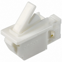
D3D-211
Description
SWITCH MINI SPDT DOOR LEVER ACT
Manufacturer
Omron
Series
D3Dr
Type
Miniature Door Switchr
Specifications of D3D-211
Circuit
SPDT
Switch Function
On-Mom
Contact Rating @ Voltage
1A @ 125VAC
Actuator Type
Angled Toggle (Detector)
Mounting Type
Panel Mount, Snap-In
Termination Style
Connector
Operating Force
204gf
Contact Form
SPDT
Contact Rating
1 Amp at 125 Volts, 0.5 Amp at 250 Volts
Actuator
Lever
Microswitch Type
Miniature
Actuator Style
Leaf Lever
Operating Force Max
204gf
Contact Voltage Ac Nom
250V
Contact Current Max
1A
Switch Terminals
Connector
Circuitry
SPDT
Body Style
Miniature
Current, Rating
1/0.5 A
Dielectric Strength
1500 VAC
Ip Rating
IP00
Mounting Hole Size
22.9x11.2 mm
Number Of Poles
1
Operation
Snap Action
Standards
UL 1054 (File No. E41515), CSA C22.2 No. 55, cuRus component recognized
Temperature Rating
-30 to 60 °C
Termination
Crimp
Voltage, Rating
125/250 VAC
Rating
1 A @ 125 VAC; 0.5 A @ 250 VAC
Operating Speed
7.5 to 500 mm/s
Operating Temperature
–30°C to 60°C
Lead Free Status / RoHS Status
Lead free / RoHS Compliant
Lead Free Status / RoHS Status
Lead free / RoHS Compliant, Lead free / RoHS Compliant
Other names
D3D211
SW748
SW748


Note: 1. Unless otherwise specified, all units are in millimeters and a tolerance of ±0.4 mm applies to all dimensions
Precautions
Be sure to read the precautions and information common to all Snap Action and Detection Switches, contained in the Technical User’s Guide,
“Snap Action Switches, Technical Information” for correct use.
■ Correct Use
Mounting
This product does not have waterproof or drip-proof construction.
Ensure that water does not enter the switch interior. In particular, do
not use the switch in locations where water may be spilled or flow
over the switch. Doing so may result in deterioration of the insulation.
Wiring
Do not use the switch with a large force applied to the connector or
lead wire. Doing so may result in rattling or contact failure.
Storage Environment
Storing the switch in a plastic bag will help prevent discoloration due
to sulfuration of the (silver-plated) terminals.
Do not use the switch in locations subject to harmful gases or to high
temperatures or humidity levels. Depending on the location, it is rec-
ommended that switches be inspected between 3 and 6 months after
the date of manufacture.
Micro Loads
Even when using the switch within the operating range, if there are
inrush currents or surges, it may decrease the durability of the
switch. If necessary, insert a contact protection circuit.
Connectors
The terminals connect to JST’s HL Connector.
The HL Connector consists of the following components.
Contact: SSF-21T-P1.4
Housing: HLP-03V
Omron does not sell the HL Connector.
Contact J.S.T. Manufacturing Co. for these connectors.
Lever Models
D3D-211
D3D-221
D3D-231
2. The operating characteristics are for operation in the A direction (indicated by the arrow)
Note: The dimensions OP1 and OP2 apply to the D3D-211 only. The D3D-221
and D3D-231 are SPST-NC and SPST-NO respectively and so therefore
have only one corresponding dimension here (OP).
10
11
6
15.7±
15
5.5
0.5
3
2
(90°)
2
A
25
9±
R1
0.5
11.4
1.5
note.)
OP2
(See
note.)
OP1
(See
■ Cautions
Handling
Do not expose the switch to shocks, such as by dropping it. Doing so
may damage or deform the switch.
Do not apply lubrication to the sliding parts, such as pushbuttons or
actuators. Doing so may result in faulty operation or contact failure.
In order to ensure stable contact force for NO contacts, use an
operating stroke of at least 5 mm.
15
OF max.
TTF max.
TT
OP min.
Miniature Door Switch
Model
Type
(NC-OFF)
D3D-211
(NO-ON)
11.5 mm
13 mm
OP1
OP2
9.7 mm (reference value)
Lever model
D3D-221
204 gf
357 gf
13 mm
D3D
D3D-231
11.5 mm
51
Related parts for D3D-211
Image
Part Number
Description
Manufacturer
Datasheet
Request
R

Part Number:
Description:
SWITCH MINI SPST-NO DOOR PLUNGER
Manufacturer:
Omron
Datasheet:
Part Number:
Description:
SWITCH MINI SPDT DOOR PLUNGER
Manufacturer:
Omron
Datasheet:
Part Number:
Description:
SWITCH MINI SPST-NC DOOR PLUNGER
Manufacturer:
Omron
Datasheet:

Part Number:
Description:
SWITCH MINI SPST-NC DOOR LEVER
Manufacturer:
Omron
Datasheet:

Part Number:
Description:
SWITCH MINI SPST-NO DOOR LEVER
Manufacturer:
Omron
Datasheet:

Part Number:
Description:
G6S-2GLow Signal Relay
Manufacturer:
Omron Corporation
Datasheet:
Part Number:
Description:
Compact, Low-cost, SSR Switching 5 to 20 A
Manufacturer:
Omron Corporation
Datasheet:
Part Number:
Description:
Manufacturer:
Omron Corporation
Datasheet:
Part Number:
Description:
Manufacturer:
Omron Corporation
Datasheet:
Part Number:
Description:
Manufacturer:
Omron Corporation
Datasheet:
Part Number:
Description:
Manufacturer:
Omron Corporation
Datasheet: