SSG-5L2T Omron, SSG-5L2T Datasheet
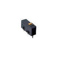
SSG-5L2T
Specifications of SSG-5L2T


Related parts for SSG-5L2T


SSG-5L2T Summary of contents
Page 1
... SSG Solder Tab (#110) PCB (see note) (see note) SSG-01T SSG-01P SSG-01T-5 SSG-01P-5 SSG-5T SSG-5P SSG-5T-5 SSG-5P-5 SSG-01L1T SSG-01L1P SSG-01L1T-5 SSG-01L1P-5 SSG-5L1T SSG-5L1P SSG-5L1T-5 SSG-5L1P-5 SSG-01L3T SSG-01L3P SSG-01L3T-5 SSG-01L3P-5 SSG-5L3T SSG-5L3P SSG-5L3T-5 SSG-5L3P-5 SSG-01L2T SSG-01L2P SSG-01L2T-5 SSG-01L2P-5 SSG-5L2T SSG-5L2P SSG-5L2T-5 SSG-5L2P-5 95 ...
Page 2
... SSG-01 series:100 m max. NO max. NC max. NC max. 2 (20G) (Contact open max., lever position: at TTP) 2 (approx. 50G) (Contact open max., lever position: at TTP) 200,000 operations min 125 VAC for SSG-5, 0 125 VAC for SSG-01, resistive OT:full) Inductive laod Inductive load Motor load 2 ...
Page 3
... N (6 gf) 1.0 mm 0.8 mm --- 18.9 mm +1.1 +1 14.4 / –0.7 –0.7 SSG-01 Crossbar PGS alloy File no. T9451449 E32667 LR21642 Hinge roller lever SSG-01L3j-5 SSG-01L2j SSG-01L2j-5 SSG-5L3j-5 SSG-5L2j SSG-5L2j-5 0.20 N (20 gf) 0.60 N 0.20 N (20 gf) (61 gf) 0. gf) 0. gf) 0. gf) 1.0 mm 0.8 mm --- 19.0 mm +1 –0.6 Hinge roller lever ...
Page 4
... Every actual model number includes the code instead of j for the kind of terminals incorporated by the model. 3. Unless otherwise specified, a tolerance of 0.4 mm applies to all dimensions. Terminal Model Solder/Tab Terminal Pin Plunger SSG-01j SSG-5j SSG-01j-5 SSG-5j-5 Hinge Lever SSG-01L1j SSG-5L1j SSG-01L1j-5 SSG-5L1j-5 Simulated Hinge Lever SSG-01L3j SSG-5L3j SSG-01L3j-5 SSG-51L3j-5 98 7.5 0.3 PT 1.8 +0.1 2 7.7 6.9 2.2 ...
Page 5
... SSG Hinge Roller Lever j SSG-01L2 j SSG-5L2 j SSG-01L2 -5 j SSG-5L2 -5 PCB Terminal Pin Plunger SSG-01P SSG-5P SSG-01P-5 SSG-5P-5 Hinge Lever SSG-01L1P SSG-5L1P SSG-01L1P-5 SSG-5L1P-5 3.8 5 0.4 t0.3 Stainless lever FP OP +0.1 2.2 –0 6.9 7.7 2 6.1 +0.1 2.2 dia. hole 0 2.5 dia. ...
Page 6
... SSG Simulated Hinge Lever SSG-01L3P SSG-5L3P SSG-01L3P-5 SSG-51L3P-5 Hinge Roller Lever SSG-01L2P SSG-5L2P SSG-01L2P-5 SSG-5L2P-5 100 3.6 6.3 0.4 R 1.3 t0.3 Stainless lever 2.87 0.1 +0.1 2 7.7 6.9 3.4 0 +0.1 2.2 dia. hole 0 Three, 1.2 0.1 2.5 dia. 9.5 0.1 Three, 0.8 5 ...
Page 7
... PT 3.5 OP 6.9 7 +0.1 2.2 dia. hole Three, 0 1.2 dia. holes 7.2 0.5 2.8 0.2 (see note) 3.2 6.4 0.2 Note: At switch bottom PCB Mounting Three, 1.35 dia. to 1.5 dia. 2.78 0.1 9.5 0.1 7.62 0.1 15.24 0.1 SSG 101 ...
Page 8
... Solder terminal is provided with a hole so that a conductor can be secured mechanically. The conductors for a soldering terminal (H type) should be flexible and its cross section should be AWG18 to 20 for the SSG-5H Series and AWG20 to 22 for the SSG-01H Series. To automatically solder the switch to a PCB in a soldering bath, com- ...