B3W-9000-R1N Omron, B3W-9000-R1N Datasheet - Page 7
B3W-9000-R1N
Manufacturer Part Number
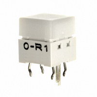
B3W-9000-R1N
Description
SWITCH TACT ILLUM SPST-NO RED
Manufacturer
Omron
Series
B3W-9r
Specifications of B3W-9000-R1N
Circuit
SPST-NO
Switch Function
Off-Mom
Contact Rating @ Voltage
0.05A @ 24VDC
Actuator Type
Square Button
Mounting Type
Through Hole
Orientation
Vertical
Outline
10.00mm x 10.00mm
Illumination
Illuminated
Operating Force
160gf
Actuator
Square
Termination Style
Pin
Body Size
10 mm L x 10 mm W x 11 mm H
Color
Milky White
Operating Temperature Range
- 25 C to + 70 C
Contact Configuration
SPST-NO
Contact Voltage Dc Nom
24V
Contact Current Max
50mA
Actuation Type
Top
Switch Terminals
Through Hole
Circuitry
SPST-NO
Rohs Compliant
Yes
Actuator / Cap Color
White
Lead Free Status / RoHS Status
Lead free / RoHS Compliant
Lead Free Status / RoHS Status
Lead free / RoHS Compliant, Lead free / RoHS Compliant
Other names
B3W-9000-R1N
B3W9000R1N
SW1040
B3W9000R1N
SW1040


B3W-9
Safety Precautions
Note:
■
Electrical Standards
Use the Switch within the rated voltage and current ranges, other-
wise the Switch may have a shortened life expectancy, radiate
heat, or burn out. This particularly applies to the instantaneous
voltages and currents when switching.
Soldering
1. Soldering Precautions
• Before any kind of soldering, test to confirm that soldering can be
• Do not solder the Switch more than twice, including rectification
2. Automatic Soldering Baths (Wave Soldering)
• Soldering temperature: 260°C max.
• Soldering time: 5 s max. for a 1.6-mm thick single-side PCB
• Preheating temperature: 100°C max. (ambient temperature)
• Preheating time: Within 60 s
• Precautions
3. Manual Soldering
• Soldering temperature: 350°C max. at the tip of the soldering iron
• Soldering time: 3 s max. for a 1.6-mm thick, single-side PCB
• Precautions: Before soldering the Switch on a PCB, make sure
Washing
Standard Switches are not sealed, and cannot be washed. Doing
so will cause the washing agent, together with flux or dust parti-
cles on the PCB, to enter the Switch, resulting in malfunction.
PCBs
The Switch is designed for a 1.6-mm thick, single-side PCB.
Using PCBs with a different thickness or using double-sided,
through-hole PCBs may result in loose mounting, improper inser-
tion, or poor heat resistance in soldering. These effects will occur,
depending on the type of holes and patterns of the PCB. There-
fore, it is recommended that a verification test is conducted before
use.
performed properly. Otherwise the Switch may be deformed by
the soldering heat depending on the type of PCB, pattern, or
lands of the PCB.
soldering. Wait for at least five minutes between the first and sec-
ond soldering to allow the temperature to return to normal. Con-
tinuous soldering may cause the casing to melt or deteriorate the
Switch characteristics.
Make sure that no flux will rise above the level of the PCB. Also
make sure that flux is not applied to the switch terminals or to the
mounting surface of the PCB.
If flux overflows onto the mounting surface of the PCB, it may en-
ter the Switch and cause a malfunction.
Precautions for Correct Use
Refer to Safety Precautions in Tactile Switches (Cat. No. X037) for details on general safety precautions.
that there is no unnecessary space between the
Switch and the PCB.
Handling
1. Usage Environment
Before installing the Switch, make sure that the area of installa-
tion is not subject to corrosive gases emitted from surrounding
parts.
Do not use in areas subject to high temperatures, high humidity,
or toxic gases such as sulfuric gas (H
(NH
sive damage to the contacts and result in malfunction.
If there is silicon in the atmosphere, it may stop the contacts from
functioning properly.
If silicon products, such as silicon oil, silicon filler, or silicon wires,
are used in the surrounding area, install a contact protection cir-
cuit to prevent arching or remove the silicon source.
The following situations may cause water to enter inside the
Switch, resulting in a malfunction due to contact failure or corro-
sion.
• Using the Switch in an outdoor environment where it is exposed
• Using the Switch in an underwater setting where it is subject to
Do not use Switches that have been dropped. The mating section
or other internal parts may be damaged, resulting in malfunction.
Operation
Do not repeatedly operate the Switch with excessive force. Apply-
ing excessive pressure or applying additional force after the
plunger has stopped may deform the disk spring of the Switch,
resulting in malfunction.
Be sure to set up the Switch so that the plunger will operate in a
straight vertical line.
If the plunger is pressed of-center or from an angle it may cause
deformation or damage to some parts. This may result in deterio-
ration of durability or malfunction.
Dust Protection
Do not install or use Switches in dust-prone environments. If a
Switch must be used in this kind of environment, use a protective
sheet or take other measures to protect it against dust.
Note:
to water drops for an extended period of time.
strong water pressure.
3
), nitric gas (HNO
Switches with high-brightness green (HG) or blue (B)
LEDs are susceptible to static electricity. Be careful when
handling a Switch with these LEDs as it may cause the
Switch to breakdown.
3
), or chlorine gas (CI
2
S, SO
2
). It can cause corro-
2
), ammonia gas
B3W-9
7
Related parts for B3W-9000-R1N
Image
Part Number
Description
Manufacturer
Datasheet
Request
R

Part Number:
Description:
SWITCH TACT ILLUM SPST-NO GREEN
Manufacturer:
Omron
Datasheet:

Part Number:
Description:
SWITCH TACT ILLUM SPST-NO RED
Manufacturer:
Omron
Datasheet:

Part Number:
Description:
SWITCH TACT ILLM SPST-NO RED/GRN
Manufacturer:
Omron
Datasheet:

Part Number:
Description:
SWITCH TACT ILLUM SPST-NO BLUE
Manufacturer:
Omron
Datasheet:

Part Number:
Description:
SWITCH TACT ILLUM SPST-NO BLUE
Manufacturer:
Omron
Datasheet:

Part Number:
Description:
SWITCH TACT ILLUM SPST-NO YELLOW
Manufacturer:
Omron
Datasheet:

Part Number:
Description:
SWITCH TACT ILLUM SPST-NO YELLOW
Manufacturer:
Omron
Datasheet:

Part Number:
Description:
SWITCH TACT ILLUM SPST-NO GREEN
Manufacturer:
Omron
Datasheet:

Part Number:
Description:
SWITCH TACT ILLUM SPST-NO GREEN
Manufacturer:
Omron
Datasheet:
Part Number:
Description:
SWITCH TACT ILLUM SPST-NO RED
Manufacturer:
Omron
Datasheet:

Part Number:
Description:
Keyswitch
Manufacturer:
Omron
Datasheet:

Part Number:
Description:
Keyswitch
Manufacturer:
Omron
Datasheet:

Part Number:
Description:
Pushbutton Switch,STRAIGHT,SPST,OFF-(ON),PC TAIL W/RETNN Terminal,PCB Hole Count:5
Manufacturer:
Omron
Datasheet:

Part Number:
Description:
Pushbutton Switch,STRAIGHT,SPST,OFF-(ON),PC TAIL W/RETNN Terminal,PCB Hole Count:5
Manufacturer:
Omron
Datasheet:

Part Number:
Description:
Pushbutton Switch,STRAIGHT,SPST,OFF-(ON),PC TAIL W/RETNN Terminal,PCB Hole Count:5
Manufacturer:
Omron
Datasheet: