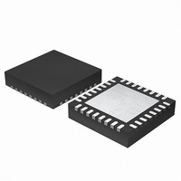
EFM32G200F64 Energy Micro, EFM32G200F64 Datasheet - Page 2

EFM32G200F64
Manufacturer Part Number
EFM32G200F64
Description
MCU 32BIT 64KB FLASH 32-QFN
Manufacturer
Energy Micro
Series
Geckor
Datasheets
1.EFM32G200F16.pdf
(63 pages)
2.EFM32G200F16.pdf
(10 pages)
3.EFM32G200F16.pdf
(463 pages)
4.EFM32G200F16.pdf
(136 pages)
Specifications of EFM32G200F64
Core Processor
ARM® Cortex-M3™
Core Size
32-Bit
Speed
32MHz
Connectivity
EBI/EMI, I²C, IrDA, SmartCard, SPI, UART/USART
Peripherals
Brown-out Detect/Reset, DMA, POR, PWM, WDT
Number Of I /o
24
Program Memory Size
64KB (64K x 8)
Program Memory Type
FLASH
Ram Size
16K x 8
Voltage - Supply (vcc/vdd)
1.8 V ~ 3.8 V
Data Converters
A/D 4x12b, D/A 1x12b
Oscillator Type
External
Operating Temperature
-40°C ~ 85°C
Package / Case
32-VQFN Exposed Pad
Processor Series
EFM32G200
Core
ARM Cortex-M3
Data Bus Width
32 bit
Data Ram Size
16 KB
Interface Type
I2C, UART
Maximum Clock Frequency
32 MHz
Number Of Programmable I/os
24
Number Of Timers
2
Operating Supply Voltage
1.8 V to 3.8 V
Maximum Operating Temperature
+ 85 C
Mounting Style
SMD/SMT
Minimum Operating Temperature
- 40 C
Lead Free Status / RoHS Status
Lead free / RoHS Compliant
Eeprom Size
-
Lead Free Status / Rohs Status
Details
Available stocks
Company
Part Number
Manufacturer
Quantity
Price
1 Errata
1.1 Chip revision C
2010-11-17 - d0021_Rev1.40
This document contains information on the errata of the latest revision of this device. For errata on older revisions, please refer to the errata history for the
device. The device datasheet explains how to identify chip revision, either from package marking or electronically.
In addition to the errata noted below, the errata for the ARM Cortex-M3 r2p0 (www.arm.com) also applies to this device.
Table 1.1. Erratas
ID
CMU6
EMU3
Title/Problem
LFXO Digital External Mode
LFXO ready flags are never set when
LFXO is configured in Digital External
Clock mode.
EM4 current
In EM4 the device may consume
700nA instead of 20nA.
Effect
When LFXOMODE in CMU_CTRL is set to DIGEXTCLK
the LFXORDY flag in CMU_STATUS and CMU_IF will not
be set when the number of cycles set in LFXOTIMEOUT in
CMU_CTRL has elapsed. Thus polling of this flag will not work.
However, the clock propagates as normal. It is only the flag
that is not set.
If EM4 is issued within a 10µS-12µS window after the 1kHz RC
oscillator rising edge transition the device will permanently con-
sume 700nA.
2
...the world's most energy friendly microcontrollers
Fix/Workaround
To detect that the clock has propagated through the ripple
counter, write to any Asynchronous Register in any Low Ener-
gy peripheral and wait for SYNCBUSY for that register field to
go low. Remember to enable the LE core clock and the clock
for the LE peripheral you choose. For example, write 0xA5 to
RTC_COMP0 and wait for COMP0 in RTC_SYNCBUSY to go
low.
There two possible workarounds for this issue.
The first workaround is using the WDOG to identify the ris-
ing edge transition and add a delay before going into EM4.
Write on the WDOG_CTRL register (for instance WDOG-
>CTRL|=WDOG_CTRL_CLKSEL_ULFRCO) and wait for the
SYNCBUSY to be released. The release of the SYNCBUSY
happens on a rising edge transition of the 1Khz clock. After
that insert a number of __NOP(); to cause a delay of 20µS
(12µS plus margin). The number of __NOP(); will depend on
the processor frequency. After the delay EM4 can be entered
safely. Note: to implement this workaround the WDOG can not
be locked, otherwise the registers will not be written.
The second workaround is by outputting the ULFRCO on a pin
(CMU_CLK0) using CMU_CTRL and CMU_ROUTE registers.
That pin should then be configured as push pull with interrupt
enable on rising edge, so the device can go to EM2 while it
waits for the ULFRCO rising edge transition. When the inter-
rupt occurs clear it and add a number of __NOP(); before en-
tering EM4, as described in the first workaround. Note: the pin
used to output the ULFRCO should be driven by an external
source.
www.energymicro.com


