EA KIT240-7LWTK ELECTRONIC ASSEMBLY, EA KIT240-7LWTK Datasheet - Page 18
EA KIT240-7LWTK
Manufacturer Part Number
EA KIT240-7LWTK
Description
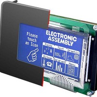
LCD Graphic Display Modules & Accessories Blue/White Contrast RS-232 Snap-In Kit
Manufacturer
ELECTRONIC ASSEMBLY
Datasheet
1.EA_KIT240-7LWTK.pdf
(20 pages)
Specifications of EA KIT240-7LWTK
Pixel Density
240 x 128
Module Size (w X H X T)
144 mm x 104 mm x 39 mm
Viewing Area (w X H)
114 mm x 64 mm
Backlighting
LED
Background Color
Blue, White
Attached Touch Screen
No
Product
Graphic LCD Module
Style
LCD Graphic Display
Interface
RS-232
Lead Free Status / RoHS Status
Lead free / RoHS Compliant


EA KIT240-7
ESC
Displays the image saved in the EEPROM with the number n1 (0..255) at position x1,y1.
Example: $1B
ESC
Displays an image at position x1,y1.
data..:
Example:
$1B $55 $4C $09 $04 $0C $0C
$0F $00 $3F $C0 $7F $E0 $76 $E0 $FF $F0 $FF $F0
$F1 $F0 $FF $F0 $6F $60 $70 $E0 $3F $C0 $0F $00
Loads the adjacent image at position 9,4.
ESC
Sets the link mode n1 for the following graphics
functions: ESC P (Set point), ESC G (Draw straight
line), ESC W (Continue straight line), ESC R R (Draw
rectangle), ESC R N (Draw rounded rectangle), ESC R M
(Fill area with pattern).
Example: $1B
Sets the link mode to inverse.
By way of example, a rectangle is drawn alongside with the link modes set, delete
and inverse on an existing background.
Link mode n1:
1 = set: black pixels irrespective of the previous value (OR)
2 = delete: white pixels irrespective of the previous value
3 = inverse: changes black pixels to white pixels and vice versa (EXOR)
4 = replace: deletes the background and sets black pixels; only area with fill pattern 'pat'
5 = inverse replace: fills the background and sets white pixels; only area with fill pattern 'pat'
ESC
Continues a straight line from the last end or point drawn to x1,y1 taking into account
the set graphics mode 'V'.
Example:
$1B $47
$1B $57
$1B $57
A straight line is drawn from 0,0 to 16,4.It is then continued to 22,27 and to 48,15.
ESC
This command suspends the KIT240 for n1/10 seconds.
Example: $1B
ESC
Reads in the input port (n1=1..8 = IN1..IN8). When n1=0, all the inputs are read in as 8-bit binary values
(MSB:IN8...In1:LSB); see application on page 5. Important: The optocouplers invert the input logic (input open:
1). The command "ESC Y I 1" puts this right (input open: 0).
Example: $1B
18
- 1 byte for the image width in pixels
- 1 byte for the image height in pixels
- Image data: number = ((width+7) / 8) * height bytes.
1 byte stands for 8 horizontal pixels on the screen; 0=white, 1=black;
MSB: left, LSB: right; the image is stored from the top down.
The BMP2BLH.EXE program on the EA DISK240 floppy disk available
as an accessory creates the image data, including the width and height,
from monochrome Windows bitmap graphics (*.BMP).
U
U
V
W
$00
$16
$30
X
Y
E
$55 $45
L
n1
$56 $03
x1 y1
$00 $10
$1B
$0F
n1
$58 $0A - After this command KIT240 waits for 1 second before next command is processed.
R
$59 $52
x1
x1
n1
y1 n1
$02
y1 data...
$04
$03 - Reads in port IN3. The result is sent via RS232.
$03
$0E - Displays image number 14 from the EEPROM at position 2,3.
Load image from EEPROM
Continue straight line
Byte 11
Byte 13
Byte 15
Byte 17
Byte 19
Byte 21
Byte 23
Byte 1
Byte 3
Byte 5
Byte 7
Byte 9
Set graphics mode
7 6 5 4 3 2 1 0 7 6 5 4
Read input port
Upload image
Bit no.
Wait/pause
Bit no.
Byte 10
Byte 12
Byte 14
Byte 16
Byte 18
Byte 20
Byte 22
Byte 24
Byte 2
Byte 4
Byte 6
Byte 8
Related parts for EA KIT240-7LWTK
Image
Part Number
Description
Manufacturer
Datasheet
Request
R

Part Number:
Description:
Display Development Tools StrEval Kit Blk-Wht w/ Intf Exp and CD
Manufacturer:
ELECTRONIC ASSEMBLY
Datasheet:
Part Number:
Description:
Display Development Tools StrEval Kit Blue-Wht w/ Intf Exp and CD
Manufacturer:
ELECTRONIC ASSEMBLY
Datasheet:
Part Number:
Description:
Display Development Tools StrEval Kit Blue-Wht w/ Intf Exp and CD
Manufacturer:
ELECTRONIC ASSEMBLY
Datasheet:
Part Number:
Description:
KIT LPC3141 SODIMM 66X48 200POS
Manufacturer:
Embedded Artists
Datasheet:
Part Number:
Description:
KIT LPC3152 SODIMM 66X48 200POS
Manufacturer:
Embedded Artists
Datasheet:
Part Number:
Description:
KIT LPC3250 259 WITH QVGA
Manufacturer:
Embedded Artists
Datasheet:

Part Number:
Description:
LCD Graphic Display Modules & Accessories Blue/White Contrast RS-232 Snap-In Kit
Manufacturer:
ELECTRONIC ASSEMBLY
Datasheet:

Part Number:
Description:
LCD Graphic Display Modules & Accessories Blue/White Contrast RS-232 Snap-In Kit
Manufacturer:
ELECTRONIC ASSEMBLY
Datasheet:

Part Number:
Description:
LCD Graphic Display Modules & Accessories Yel/Green Backlight RS-232 Snap-In Kit
Manufacturer:
ELECTRONIC ASSEMBLY
Datasheet:

Part Number:
Description:
LCD Touch Panels Touchpanel Analog for DOGM128-6
Manufacturer:
ELECTRONIC ASSEMBLY
Datasheet:
Part Number:
Description:
LCD Touch Panels Touchpanel Analog For DOGS102
Manufacturer:
ELECTRONIC ASSEMBLY
Datasheet:
Part Number:
Description:
LCD Touch Panels Touchpanel Analog For DOGXL160
Manufacturer:
ELECTRONIC ASSEMBLY
Datasheet:
Part Number:
Description:
LCD Touch Panels Touchpanel Analog For DOG-L128-6
Manufacturer:
ELECTRONIC ASSEMBLY
Datasheet:

Part Number:
Description:
LED Displays Bezel 017-xx Series 75.0x24.2/ 91.0x36.4
Manufacturer:
ELECTRONIC ASSEMBLY
Datasheet: