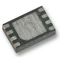
SP7686AER-L Exar Corporation, SP7686AER-L Datasheet - Page 12

SP7686AER-L
Manufacturer Part Number
SP7686AER-L
Description
LED Drivers Driver in 2x3 DFN
Manufacturer
Exar Corporation
Series
-r
Datasheet
1.SP7686AER-L.pdf
(16 pages)
Specifications of SP7686AER-L
High Level Output Current
500 mA
Operating Supply Voltage
2.7 V to 5.5 V
Maximum Supply Current
3 mA
Maximum Power Dissipation
Internally Limited
Maximum Operating Temperature
+ 85 C
Mounting Style
SMD/SMT
Package / Case
DFN-8
Minimum Operating Temperature
- 40 C
Constant Current
Yes
Constant Voltage
-
Topology
PWM, Step-Down (Buck), Step-Up (Boost), Switched Capacitor (Charge Pump)
Number Of Outputs
1
Internal Driver
-
Type - Primary
Flash/Torch, General Purpose
Type - Secondary
High Brightness LED (HBLED), White LED
Frequency
2MHz ~ 2.8MHz
Voltage - Supply
2.7 V ~ 5.5 V
Voltage - Output
-
Mounting Type
Surface Mount
Operating Temperature
-40°C ~ 85°C
Lead Free Status / RoHS Status
Lead free / RoHS Compliant
Available stocks
Company
Part Number
Manufacturer
Quantity
Price
Company:
Part Number:
SP7686AER-L
Manufacturer:
SIPEX
Quantity:
5 000
Company:
Part Number:
SP7686AER-L/TR
Manufacturer:
TI
Quantity:
35 679
Part Number:
SP7686AER-L/TR
Manufacturer:
SIPEX
Quantity:
20 000
APPLICATIONS INFORMATION
CONT’D
The SP7686 charge pump circuit requires 3
capacitors: 10μF input, 2.2μF output and
0.22μF
recommended. For the input capacitor, a value
of 10μF will help reduce input voltage ripple
for applications sensitive to ripple on the
battery voltage. All the capacitors should be
surface mount ceramic for low lead inductance
necessary at the 2.4MHz switching frequency
of the SP7686 and to obtain low ESR, which
improves bypassing on the input and output
and improves output voltage drive by reducing
output resistance. Ceramic capacitors with
X5R
recommended
selection
included in Table 1 below.
The input and output capacitors should be
located as close to the V
possible to obtain best bypassing, and the
returns should be connected directly to the
PGND pin or to the thermal pad ground
located under the SP7686. The fly capacitor
should be located as close to the C1 and C2
pins as possible. See the RECOMMENDED
LAYOUT
recommended layout.
To obtain low output ripple, a value of 2.2μF is
recommended for C
the value for C
For best regulation and low input current
ripple the input capacitor value of 10μF is
recommended.
© 2010 Exar Corporation
Murata/www.murata.com
Murata/www.murata.com
Murata/www.murata.com
Murata/www.murata.com
Murata/www.murata.com
TDK/www.tdk.com
TDK/www.tdk.com
TDK/www.tdk.com
TDK/www.tdk.com
TDK/www.tdk.com
Manufacturers/
or
Website
fly
section
of
X7R
FLY
recommended
for
A smaller 4.7μF for Cin will
capacitor
of 0.22μF is recommended.
temperature
OUT
for
most
. For all output currents
GRM188R60J106ME19D
GRM155R60J224KE19D
GRM155R60J105KE19D
GRM188R60J225KE19D
GRM188R60J475KE19D
IN
C1608X5R0J107M
C1005X5R0J224K
C1005X5R0J105K
C1608X5R0J225K
C1608X5R0J475K
details
Part Number
and V
applications.
are
capacitors
C
C
o
o
grade
OUT
n
n
s
on
s
Table 1: Capacitor Selection
typically
t
t
pins as
a
a
n
n
t
t
are
the
is
C
C
A
Capacitance/
12/16
u
u
r
r
0.22uF/6.3V
0.22uF/6.3V
Voltage
r
2.2uF/6.3V
4.7uF/6.3V
2.2uF/6.3V
4.7uF/6.3V
r
10uF/6.3V
10uF/6.3V
e
e
1uF/6.3V
1uF/6.3V
work but input voltage ripple will increase and
may effect regulation.
R
and Flash modes so the sense resistor R
determined by the value needed in the Torch
or Flash mode for the desired output current
by the equation:
R
R
Once the R
one mode, the I
other mode using the following equation:
I
Using an example of Torch current of 180mA
and Flash current of 450mA, calculated R
for Torch is 0.06 /0.180 = 0.333 Ohms. Use a
standard value of 0.33 Ohms. I
mode is 0.16/0.33 = 480mA
The power obtained in the Flash mode would
be:
P
The typical 0603 surface mount resistor is
rated 1/10 Watt continuous power and 1/5
Watt pulsed power, more than enough for this
application. For other applications, the P
power can be calculated and resistor size
selected. The R
to be size 0603 for most applications. The
range of typical resistor values and sizes are
shown here in Table 2.
n
n
The 7686A part has fixed FB voltages in Torch
OUT
FLASH
SENSE
SENSE
ESISTOR
t
t
F
F
= V
l
l
=V
=V
= V
a
a
s
s
FB
FB
FB
h
h
FB
/I
/I
/ R
Size/Type/Thickness
S
SENSE
D
D
OUT
OUT
*I
0402/X5R/0.55mm
0402/X5R/0.55mm
0402/X5R/0.55mm
0402/X5R/0.55mm
ELECTION FOR THE
0603/X5R/0.9mm
0603/X5R/0.9mm
0603/X5R/0.9mm
0603/X5R/0.8mm
0603/X5R/0.8mm
0603/X5R/0.9mm
SENSE
r
r
OUT
i
i
where V
where V
v
v
Capacitor
SENSE
resistor has been selected for
e
e
= 160mV*480mA ~ 77mW.
OUT
r
r
S
S
i
i
P
P
n
resistor is recommended
n
can be selected for the
7
7
FB
FB
D
D
6
=60mV (Torch Mode)
=160mV(Flash Mode)
6
F
F
8
8
N
N
6
6
2
2
/
/
m
m
SP7686A
S
S
OUT
m
m
P
P
100kHz
ESR at
7
7
Rev. 2.1.0
x
for Flash
x
0.05
0.03
0.03
0.02
0.02
0.05
0.03
0.03
0.02
0.02
6
6
3
3
SENSE
8
8
m
m
SENSE
6
FLASH
6
m
m
A
A
is


