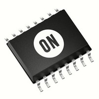
CAT4106YP-T2 ON Semiconductor, CAT4106YP-T2 Datasheet - Page 12

CAT4106YP-T2
Manufacturer Part Number
CAT4106YP-T2
Description
LED Drivers LED DRVR BOOST 4CH/10LED
Manufacturer
ON Semiconductor
Datasheet
1.CAT4106HV4-GT2.pdf
(15 pages)
Specifications of CAT4106YP-T2
Number Of Digits
4
Low Level Output Current
10 mA
High Level Output Current
175 mA
Operating Supply Voltage
- 0.3 V to 6 V
Maximum Supply Current
4.4 mA
Maximum Operating Temperature
+ 85 C
Mounting Style
SMD/SMT
Package / Case
TSSOP-16
Minimum Operating Temperature
- 40 C
Lead Free Status / RoHS Status
Lead free / RoHS Compliant
Available stocks
Company
Part Number
Manufacturer
Quantity
Price
Company:
Part Number:
CAT4106YP-T2
Manufacturer:
ON Semiconductor
Quantity:
1 978
Company:
Part Number:
CAT4106YP-T2
Manufacturer:
ON Semiconductor
Quantity:
950
Application Information
External Component Selection
Capacitors
on the VIN pin (C1), 4.7 mF on the inductor input (C2), and
10 mF on the output (C3). Under normal condition, a 4.7 mF
input capacitor (C2) is sufficient. The voltage rating of each
capacitor should be compatible with the maximum voltage
applied. For the output, a 50 V rated capacitor (C3) is
recommended in case the LED becomes disconnected
(Open−LED condition). X5R and X7R capacitor types are
ideal due to their stability across temperature range.
Inductor
In cases where the efficiency is critical, inductances with
lower series resistance are preferred. Inductors with current
rating of 1 A or higher are recommended for most
applications. Coilcraft CR73−470 inductor rated at 1.08 A is
recommended for most applications.
Schottky Diode
the peak current flowing through it. A 1 A rated Schottky
diode is recommended. The Schottky diode performance is
rated in terms of its forward voltage at a given current. In
order to achieve the best efficiency, this forward voltage
should be as low as possible. The response time is also
critical since the driver is operating at 1 MHz. NXP
PMEG6010CEJ (60 V / 1 A rated) Schottky barrier rectifier
is recommended for most applications.
The CAT4106 requires small ceramic capacitors of 1 mF
A 47 mH inductor is recommended for most applications.
The current rating of the Schottky diode (D) must exceed
http://onsemi.com
12
Recommended Layout
through the PCB. Multiple via can be used to connect the tab
of the CAT4106 to a large ground plane underneath the
package.
IC as possible. The RSET resistor (R1) and channel voltage
setting resistor (R3) should have a Kelvin connection to the
GND pin of the CAT4106.
The board layout should provide good thermal dissipation
Input capacitor C1 should be placed as close to the driver
Figure 29. Recommended Layout for TQFN−16


